By Matt Evans, Future Facilities
At the heart of any server, PC or mobile phone is a microprocessor – a multipurpose, digital integrated circuit that accepts binary data as input, processes it according to a set of stored instructions, and outputs the results. More simply, microprocessors are the brain of computers, capable of performing hundreds of billions of calculations per second.
This impressive performance comes at a cost, however, requiring a lot of electrical power, all of which dissipates as heat. This heat needs to be managed to prevent system failure, which requires an accurate model of the way heat dissipates from individual components.
Microprocessor History
In 1971, Integrated Electronics (Intel) invented the world’s first microprocessor – Intel 4004. The device ran at a clock speed of 108kHz, but at processing only 4 bits at a time, it could only represent signed numbers in the range 18 to +7. This made it unsuitable for arithmetic calculations but suitable for controlling devices.
The next step also came from Intel, the following year, in the form of the first 8-bit microprocessor. The Intel 8080 was a refined version, becoming the most commercially-popular 8-bit microprocessor.
Over the next decade, Intel moved through the gears: In 1978 it released a 16-bit microprocessor, the 8086, that could represent signed numbers in the range of -32,768 to +32,767. In 1985, it introduced a 32-bit microprocessor, the 80386, that could represent signed numbers in the range ±2×10⁹. Both of these third- and fourth-generation iterations, with their increased range of signed numbers, were widely used in arithmetic and number-crunching operations.
From 1995 to today, high-performance, high-speed microprocessors are 64-bit devices. Smartphones, tablets and laptops are much faster because of them, with greater storage capabilities than the mainframe computers of the past, yet at a fraction of the cost.
A Typical Integrated Circuit Component
Gordon Moore, co-founder of Intel, observed that the number of transistors in a dense integrated circuit (IC) doubles approximately every two years. Since the early 1970s, microprocessor transistor-counts have increased from several thousand to over ten billion. Because each transistor requires power function, microprocessors are then dissipating enormous power in a relatively small footprint. A modern Intel Xeon E5-2600 v4, for example, has a heating power density of 31W/cm2, a vast contrast to the1971’s Intel 4004 of approximately 8W/cm2.
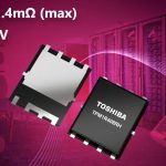
In its simplest form, an IC consists of a die attached to a substrate housed inside an encapsulant with either leads or solder balls attaching the component to a PCB. The die is slither of electronic-grade silicon on which a circuit is fabricated and is the point inside the component where heat is generated. The substrate is essentially a miniature PCB on which the die is mounted and, much like a PCB, consists of an insulator material and conductive traces. A more complex component such as a microprocessor can contain multiple dies and other subcomponents such as on-chip capacitors.
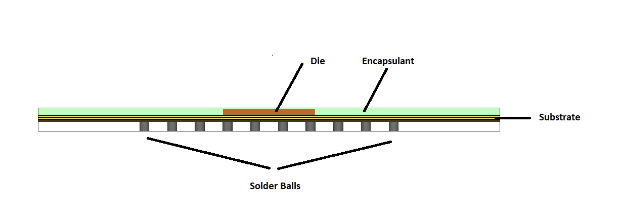
Figure 1- Diagram of a typical IC component
Internally, heat is transferred from the die to the substrate and encapsulant via conduction. The way heat is lost externally to the surroundings can vary drastically, depending on the application. In the simplest of cases, a component could be cooled by natural convection, with heat lost externally to the surroundings through a mixture of conduction at the bottom surface, and convection and radiation at the sides and top surface.
In a server-type application, a component would, most likely, be cooled by forced convection. A component will still conduct heat to the PCB from the bottom, but, at the top, heat will typically be conducted to a heatsink that’s cooled by convection; radiation effects become negligible in this scenario.
Inside a mobile phone, a component would typically conduct heat either via heat pipes or directly to the gadget’s outer casing. In this application, convection inside the casing would be irrelevant as there is very little free space.
In each of these applications, the split as to how much heat is removed from the component by each of the three mechanisms very much depends on the internal component structure.
Five Things to Consider When Modelling Microprocessors
Microprocessor manufactures can use simulation to design, test and characterise a component under laboratory conditions. Component models are supplied to customers, to ensure that their design provides enough cooling to prevent component failure.
Here are five things to consider when simulating and sharing thermal models of microprocessors:
1. Thermal expansion
Inside a component, there are several dissimilar materials bonded together. Die, substrate and other sub-components expand at different rates as temperature increases, carrying the risk of damaged sub-components, with broken attachments to the substrate that can ultimately lead to a catastrophic failure.
Whilst thermal expansion can’t be modelled directly in most CFD tools, it is important to have an accurate prediction of temperature, so that engineers can determine whether this could lead to failure caused by expansion.
Accurate temperature prediction depends on more than supplying the correct material properties.

Figure 2: A component close-up built in 6SigmaET showing the die boned to a multi-layer substrate
2. Thermal throttling
To prevent system failure, components are often designed to have their power throttled when a specific temperature is reached. Throttling is a process of reducing component power – and therefore speed – temporarily until temperatures are back in the acceptable range.
In 6SigmaET, throttling can be modelled in a number of ways: First, multiple power profile curves can be specified alongside a transition temperature defining, when the component will switch to a different power profile. This allows various stages of throttling to be applied, depending on how high temperatures rise.
More complex throttling schemes can be modelled by interfacing with an external dynamic link library (.dll) defining the throttling scheme. Data can be exchanged during solve time, and the component’s power dissipation controlled accordingly.

Figure 3: Multiple power profiles and transition temperatures, modelled in 6SigmaET
3. Components can be defined parametrically
Each component design is unique, however most fall into specific component types, so generic component libraries help. In 6SigmaET for example, the ‘Component Package Builder’ allows you to parametrically define five common component types. Using this tool, it might not be possible to create the exact desired geometry but it’s a good starting point from which to make minor modifications.

Figure 4: 6SigmaET component package builder can be used to parametrically define components
4. Sharing detailed components
In the past, sharing component models was a difficult process, even internally, as different teams use different simulation tools, with each simulation tool supported only by its own native file formats. However, it is now possible to share models seamlessly between tools using the vendor-neutral ECXML file format. ECXML is analogous to STEP or IGES files in the world of CAD, allowing thermal models including geometry, power dissipations and material properties to be shared between the main three electronics thermal simulation tools: 6SigmaET, FloTHERM and Icepak.

Figure 5: EXCML can be used to export and share thermal models of components
5. Create a DELPHI compact thermal model
A DELPHI Compact Thermal Model (CTM) is a simplified way of representing a detailed component. Complex aspects of geometry are replaced with 2D nodes connected by a network of thermal resistances. These resistances are calculated from the results of dozens of predefined simulations specified in the JEDEC standard, ensuring that the CTM provides an accurate representation of the detailed model for almost any scenario.
CTMs have several benefits; they are less computationally-expensive to model than detailed components. They also allow component manufacturers to supply accurate thermal models of their component whilst maintaining the secrecy of how they are constructed.
Figure 6- DELPHI CTM’s can be used to simplify a detailed component modelled whilst still maintaining accuracy
Create and Share
Ever-increasing power densities make microprocessor thermal design increasingly challenging. To ensure component robustness and that of the systems they are incorporated in, simulation is a must at all stages of the supply chain.
Thermal simulation allows component designers to design, test and characterise a component under laboratory conditions. This model can then be supplied to customers, to enable them to design their own systems that keep the component within its thermal limits.
The creation and sharing of accurate thermal models require a simulation tool capable of accurately predicting temperatures and simulating modem thermal throttling techniques.