By Mark Patrick, Mouser Electronics
When it comes to technical innovation in the electronics industry, some components remain applicable for a lot longer than anyone could have predicted. Many engineers might think of the 555 or 741 as good examples – 40 years on from their initial launch, both are still used in many new designs and are subject of interest at schools and colleges.
The magnetron is another example, since today it still features in commercial and domestic microwave ovens seven decades after its introduction. In fact, the magnetron belongs to a broader Class of products known as thermionic valves, or ‘tubes’. Valves were relegated to specialist applications once the semiconductor transistor came to dominate. Compared to transistors, valves were oversized, generated too much heat and required multiple high-voltage rails. Nevertheless, they are still found in many high-end audio applications, such as amplifiers and pre-amplifiers. And, reassuringly, their numbers in designs continue to grow, with many musicians demanding them in amplifier systems.

Interest in Valves
The primary reason often quoted for this continued interest in valves is that the music coming from a valve-based amplifier sounds “warmer” and “richer”, which a transistor is “unable to reproduce as faithfully as a valve can”. Over the years, in an attempt to levy scientific fact behind the myth, audio equipment manufacturers, such as Quad, as well as academics from the world of physics, have attempted to analyse why such preferences have come about.
From technical perspective, valves used in the final stages of an audio amplifier have, without a doubt, proved to be more electrically-resilient than their transistor counterparts. When faced by a short or open circuit, valves tend to be protected by their output transformer, whereas transistor-based amplifiers typically use the speaker coils as load. Unless suitable protection devices are applied, the transistors can easily be destroyed.
Transistors are also not particularly good at dealing with high-voltage transients and high operating temperatures, the latter resulting in thermal runaway and over-current conditions. Protection circuitry is straightforward and easy to implement but adds to the bill-of-materials (BoM) and takes up more space.
It appears that the warmer, more organic sound mainly comes from overdriving the amplifier, as rock guitarists do, such that it creates a series of even-order harmonics. Such harmonics – a feature of a single-ended Class A amplifier designs – are not so prevalent in the far more efficient Class AB and Class B push-pull amplifier designs where the crossover (the point at which one device switches over to the other) introduces distortion and odd-order harmonics. Even-order harmonics add sound ‘warmth’, whereas, by contrast, odd-order harmonics tend to introduce a harshness and dissonance into the output. To understand how these two forms of harmonics come about, let’s look a bit closer into the differences between the amplifier classes.
Amplifier Classes
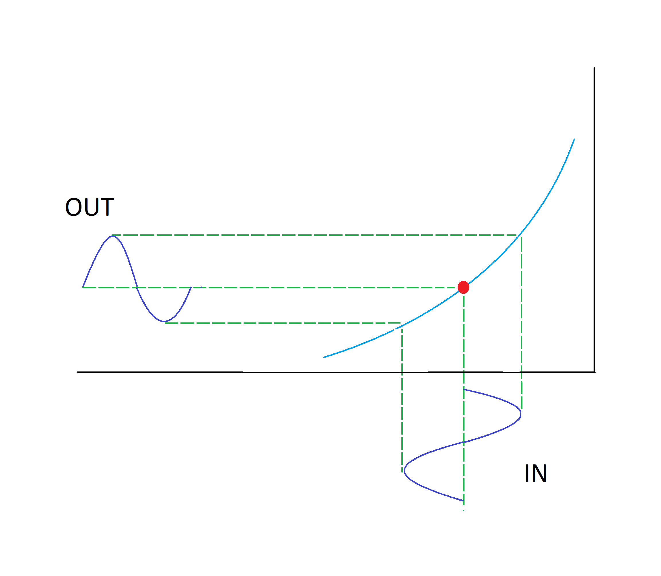
A Class A amplifier is always conducting, drawing current even when there’s no input signal, the reason why they are not so power-efficient. Figure 2 shows this, with the input signal biased to the ideal mid-point of the valve’s operating curve. Note that the output signal never drops to zero.
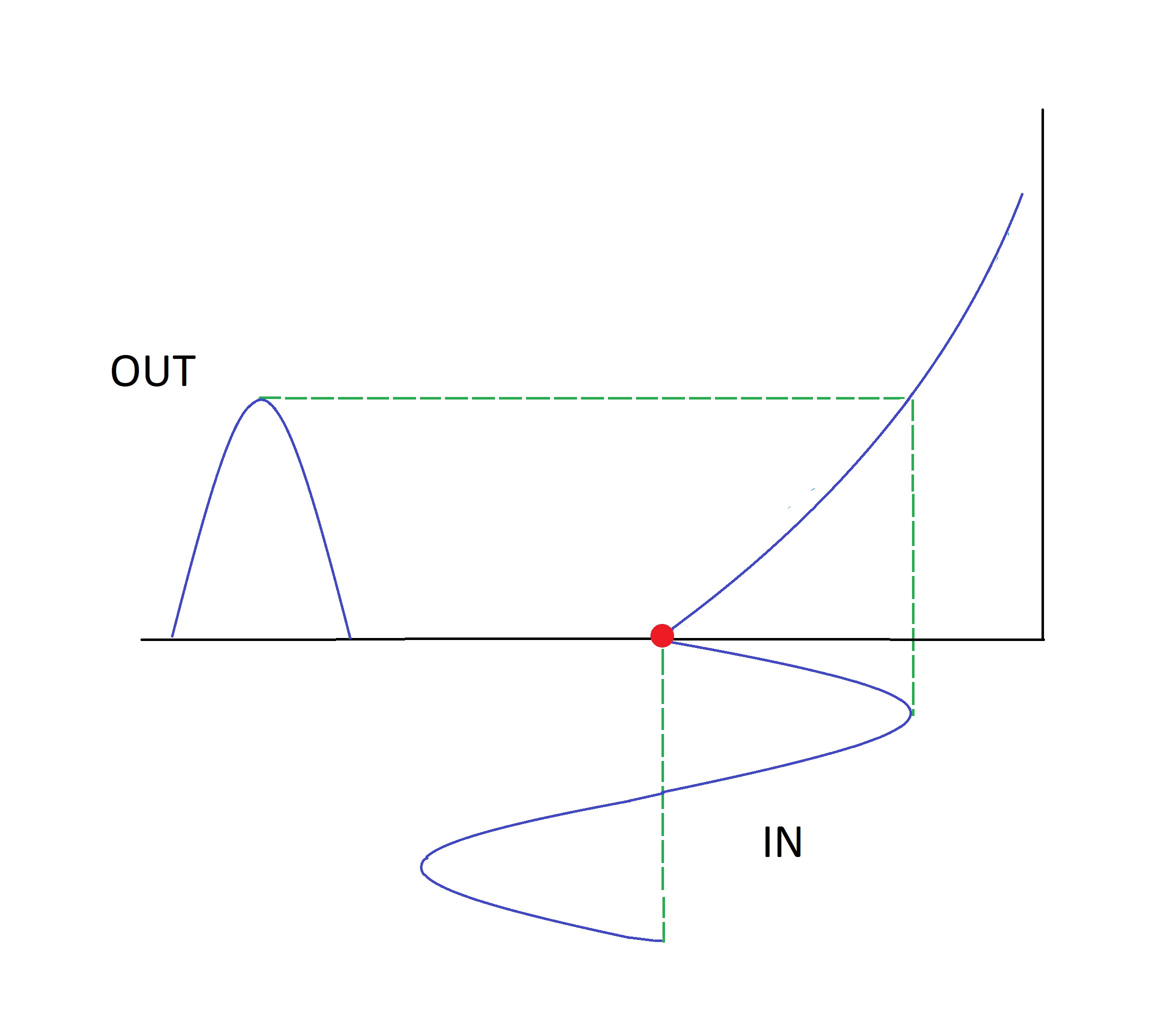
A Class B valve amplifier operates with the input signal biased to the point that the valve almost stops conducting, only creating an output on the positive part of the input signal. For this reason, to accurately reproduce the input signal, it is necessary to create a corresponding output stage for the other part, which corresponds to the negative part of the sine wave shown in Figure 3.
This push-pull arrangement, therefore, requires two valves. Compared to the Class A operating curve you’ll notice that the Class B amplifier requires a larger input signal to achieve the same output, thus making it harder to overdrive it. Although power-efficient, this approach has a major drawback: distortion is introduced at the switching crossover between the two valves; see Figure 4.

In an attempt to lessen the impact of crossover distortion, the Class AB amplifier employs a push-pull configuration, but the inputs are biased slightly up the operating curve of each valve. With this approach, the efficiency levels derived are significantly better than for a straight Class A amplifier, and the crossover distortion is reduced.
Achieving the overdriven sounds that rock guitarists seek comes from pushing the input signal so high up the valve’s operating curve that it no longer provides any more output, flattening out the output peaks or clipping the input. Mid-range through to the highest input signals all end up amplified to maximum, while the clipping also introduces a mixture of harmonics to the output. Such harmonic additions and overdriven distortions do not have to occur in the final stages of an amplifier but can be created in the pre-amplifier, leading to a hybrid amplifier concept.
A hybrid amplifier typically has a valve-based pre-amplifier followed by a solid-state final stage. The sound’s warmth is introduced at the pre-amplifier stage, while the space-efficient solid-state devices yield the raw amplification power required. This hybrid approach has now become almost de facto across the music industry, with top amplifier brands such as Marshall, ORANGE and VOX featuring a hybrid amplifier lineup.
Glossy Future for the Valve
There’s little sign that the humble thermionic valve is being consigned to the dustbin anytime soon. In fact, the hybrid-amp approach has encouraged some manufacturers to reintroduce or expand their line-up of valve guitar amplifiers, using valves in both the pre-amplifier and the final stages. So much so that Music Radar’s annual review of the best guitar amps under £1000 ($1,300) states that the majority of them are valve-based. Many of these amplifiers use the EL84 power pentode valve in their final stages and the EL34 or ECC83 in the pre-amplifier. Considering that the EL84 and the ECC83 were introduced in 1954 and the EL52 in 1952 they have all surpassed the earlier-mentioned semiconductor devices in terms of production life.
One recent high-end amplifier development has even gone so far as to emulate the physical appearance of a valve, in this case the veteran KT88, by fabricating a 200W power gallium nitride (GaN) MOSFET amplifier inside the valve’s glass envelope. All connections of the GaNTube are made through the KT88’s original octal socket base, and LEDs provide the valve’s distinctive amber glow. Placed centrally on top of a minimalist chassis, the GaNTube provides a focal point of the sleek and elegant Vivace Hi-End Monoblock amplifier. And, no, you can’t swap a GaNTube with a KT88!
Whether it is a full amplifier set-up, a hybrid arrangement, or just a semiconductor device trying to mimic a retro feel, the valve clearly still has a valued place in audio technology. And if you wanted further convincing that the valve’s popularity is rising once again, take a look at your phone’s music equaliser settings, since it is highly likely it has a tube (valve) amp option.