By Abhinay Patil, Field Applications Engineer, Analog Devices
Question:
I changed one of my devices to a newer and better part with lower current consumption. Nothing is working any more, and even the new burnt out. What’s the explanation for this?
Answer:
Linear regulators are fairly simple devices and don’t have too many challenges. That said, however, you can still get into trouble with them occasionally.
In my role as a field applications engineer, there are times when customers ask me to recommend a drop-in replacement for a part they’re using from another supplier. In many of these cases, the decision to replace a part is made by the customer’s production or purchase team, and the original circuit designer may not be aware of the change.
The decision process is fairly simple, and the alternative part should have the same functionality, package and pin configuration, as well as equal or better electrical specification when compared to the device it replaces. Once all these boxes are checked, you provide the necessary comparison data to the component engineer, and the new component is added to the bill of materials as a second-source alternative. At this stage it’s all set, or at least until the product that worked faithfully with the older component begins to fail on the production line following the replacement. What went wrong?!
A Typical Scenario
I was involved in one such case where we followed this “replacement” process with an ADI isolated RS-485 transceiver acting as a replacement for another supplier’s device. The devices were form-, fit- and functionality-compatible. The customer went ahead and ordered a large quantity of this part, with no reason to suspect anything going wrong. However, the new RS-485 transceiver started failing on the production test-bed. Since nothing else in the design had been changed, it came down to the new device.
We found that the linear regulator powering the bus side of the transceiver was not regulating down to 5V as expected, but instead was reaching a much higher voltage. We had to carefully review and compare the old and new transceivers’ datasheets, as well as that of the linear regulator, to figure out what was going wrong.
“Better” is a qualitative term and depends on the parameter in question. For example, when it comes to speed/CMRR/PSRR, higher is better; when it comes to offset voltage/drift, lower is better; and you don’t need great engineering insight to know that when it comes to power consumption, lower is always better. Or is it? In this particular case, it turned out it wasn’t. The older transceiver consumed 15mA (typically) on the bus side in idle state, while the new device consumed only 2mA (maximum). It was no wonder that the new device looked better on paper. Unfortunately, the linear regulator didn’t seem to agree and went berserk.
Linear Regulators
As mentioned before, linear regulators are fairly simple devices that don’t have too many demands. Their one peculiar requirement, however, is that they need a minimum load current to function properly. If this condition is not met, the regulator stops regulating correctly and the output voltage goes out of bounds. The situation could also get worse if the regulator’s input voltage is much higher than the desired output voltage.
Many modern linear regulators have been carefully designed to address this and pose no such problems. Some of the older devices (like the one in the customer’s design) don’t, and so need extra precautions during system design. In some cases, the feedback resistor network for the adjustable output LDO takes care of the minimum load current. Unfortunately, one could run into this issue inadvertently by deciding to supersize these resistors while keeping the ratio the same. There could also be other scenarios where the device being powered by the LDO meets the load requirement during normal operation, but not whilst in standby.
These are all potential pitfalls to watch out for, so be sure to read the LDO’s datasheet carefully. If there’s a minimum load current requirement, it would usually say so in some way. Figure 1 shows a couple of examples.
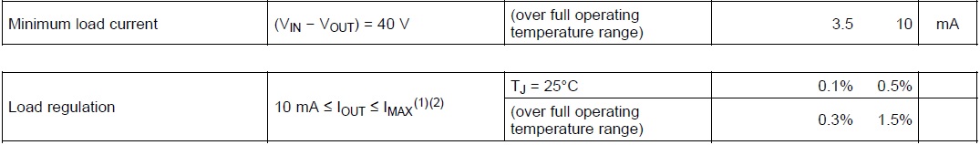
Figure 1. An example of minimum load current from a datasheet

Figure 2. (Left) The regulator operating correctly with the older device (minimum load current requirement satisfied). (Right) The unstable regulator with the new device (load current not sufficient)
A Simple Fix
Going back to our story: once the root cause of the problem was understood, it was fairly simple to fix. All we had to do was add a bleeder resistor on the regulator output, to draw the minimum load current.
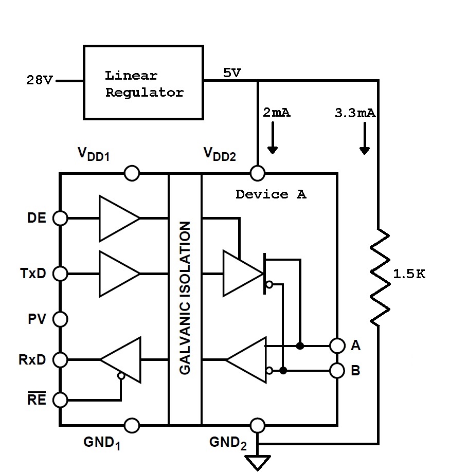
Figure 3. The problem resolved after adding a bleeder resistor to draw minimum required load current