By Fehmi Sevilmiş and Hulusi Karaca, Selçuk University, Turkey
Fossil-based energy sources have had significantly influenced human life, but not always positively, considering their impact on the climate. Now we are beginning to see a rise in environmentally-friendly renewable energy sources (RES), one of which is wind energy. This type energy generation is clean, economic, sustainable and reliable.
Countries like China, the US, Germany and Denmark are all increasing their production of electricity from wind energy. The annual and cumulative installed global wind power values in 2002-2017 are shown in Figures 1 and 2, respectively. In 2017, globally the installed wind power capacity was close to 52.5GW. The cumulative global installed wind power by the end of 2017 reached 539GW.


Wind Energy Systems
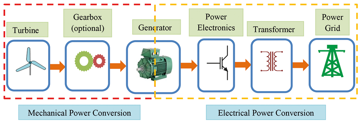
A fundamental power pattern of a wind energy system is composed of two parts: mechanical and electric (see Figure 3). The mechanical part rotates a shaft providing energy from the wind, whereas the electric one is responsible for transforming it into electricity suitable for the power grid. The two parts are connected via an electric generator, which is an electromechanical system that converts mechanical energy into electricity. To be able to feed this electricity into the grid, it needs regulating with a power electronics converter, see Figure 3.
A transformer is used to boost the voltage level to that of the grid. It also enables more efficient power transmission and blocks any DC current entering the power grid. Overall, wind energy becomes an easily regulated and controlled source of power.
Grid Synchronisation
Grid synchronisation is an important aspect of connecting a grid-side converter (also known as grid-interactive inverter) to the grid. To operate in sync with the power grid, an algorithm is needed, called “synchronisation algorithm”. To control the inverter, the phase angle of the grid voltage must be determined quickly and accurately.
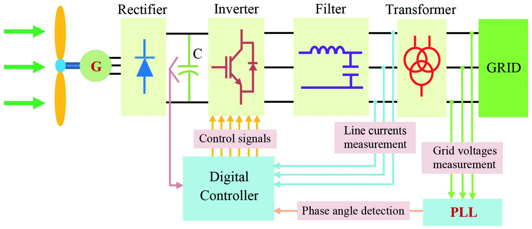
Figure 4 shows a grid-synchronisation block diagram for a wind-energy system. The phase voltages of the grid are measured by sensors and the synchronisation algorithm determines their phase angles. The detected phase angle is then exported to a digital controller, which generates the control signals for the inverter, keeping it synchronised with the power grid.
Conventional and Fuzzy-Based PLL Algorithms
Phase locked loop (PLL) algorithms are widely used in three-phase on-grid systems for grid synchronisation because they are simple, easy to implement and perform well.
The PLL operates as a feedback system to instantaneously detect the phase angle (θ) of the grid voltages. Figure 5 shows a basic block diagram of a conventional PLL.
In a PLL system, the measured three-phase grid voltages (Va, Vb and Vc) are first converted into rotating axes variables (Vd and Vq), which are DC components.

Under ideal grid conditions, the determined phase angle (θ*) is equal to the phase angle of the grid (θ) and, as can be seen from the equations below, if Vq is zero, Vd is equal to the peak value of the grid voltage; Vq includes information about the grid’s phase angle error, and Vd gives the amplitude information of the grid voltage in steady state.

In the control algorithm of the PLL, it is very important that the obtained phase angle is locked fast to the phase angle of the grid and that it has good filtering characteristics for the system’s dynamic performance. A proportional integral (PI) controller is normally used for PLL control. It also operates as a loop filter in the system, which controls the Vq voltage and determines the system’s dynamics. Under non-ideal grid conditions such as unbalanced or distorted grid, setting the PI coefficients (KP and KI) keep the system stable. But, in different imbalance and distortion situation, the phase angle (θ*) can be incorrectly calculated for the same KP and KI values. Furthermore, even if KP and KI are updated according to the variable conditions, the phase angle is still improperly estimated and synchronisation time increases.
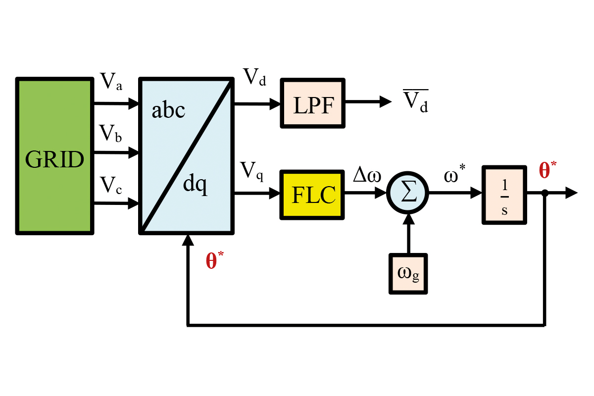
To improve the dynamic response of the conventional PLL and estimate the phase angle quickly and accurately under non-ideal grid conditions, it is necessary to use an adaptive control algorithm. In this study, we use a fuzzy logic controller (FLC) instead of a PI controller; see Figure 6. In addition, we added a low-pass filter (LPF) to obtain a mean value of Vd (Vd) very close to the real Vd value. In this context, using an FLC is more convenient than a PI controller. FLC has non-linear, adaptive control mechanism and robust performance in various conditions, and is one of the most intelligent control algorithms. Thanks to its non-linear and adaptive structure, FLC is suitable to use in grid conditions where changes can occur, including unbalanced and distorted grid conditions.
Simulation Results
We tested the PI-controlled classical PLL method and a simulated the fuzzy-controlled PLL method under two different grid conditions – unbalanced and distorted. In the conventional PLL method, we calculated the PI coefficients KP = 0.74 and KI = 85.05 taking into account that the damping ratio of the PLL loop filter is ξ = 0.707, the natural frequency is ωn = 162.63rad/s and the settling time is two periods, or 40ms.
In fuzzy PLL, we determined the Vq error and the variation of the Vq error (derivative) as input variables and designed the angular frequency variation of the grid (Δω) as output variable. Furthermore, we expressed each input and output variable with a 7-triangular membership function, using the Mamdani-type fuzzy inference mechanism.
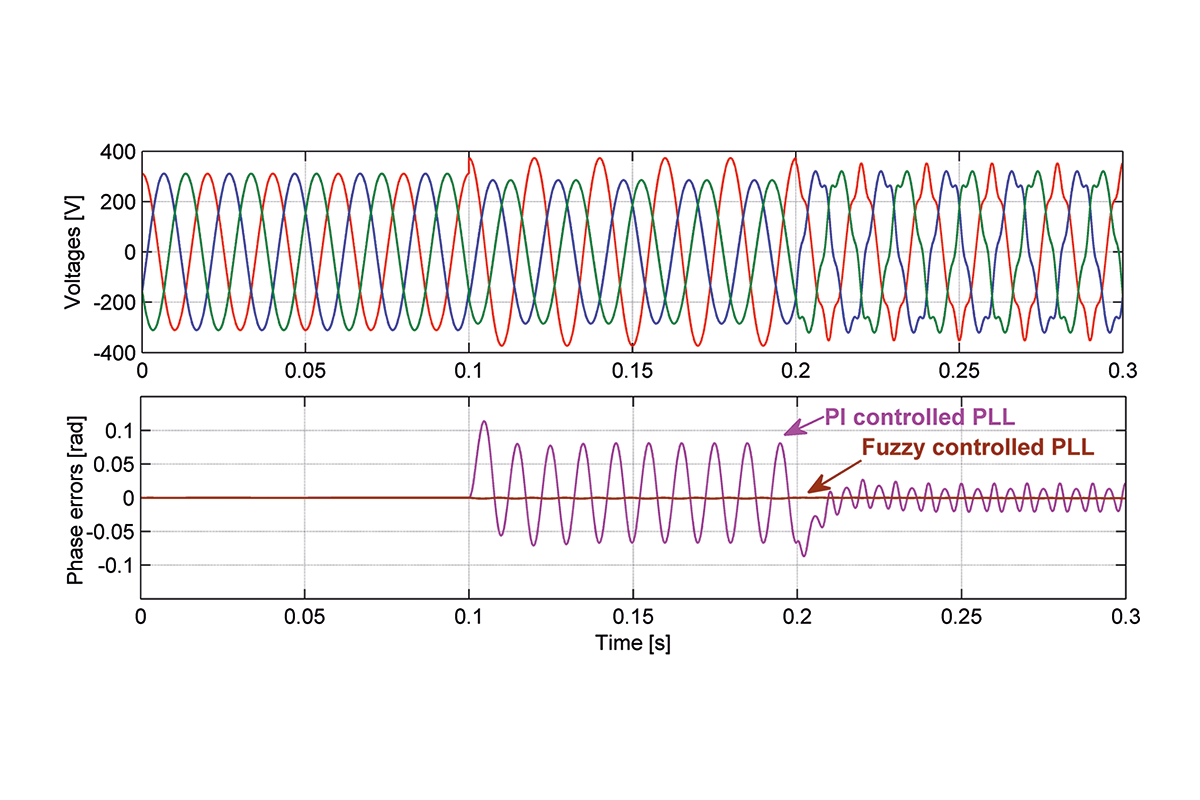
As shown in Figure 7, we set the three-phase grid voltages to a peak value of 311V and the grid frequency at 50Hz for a 0-0.1s time interval under a balanced grid condition, we didn’t include a phase error for either method. Following that, we tested the PLL methods under an unbalanced grid condition at 0.1-0.2s (as unbalanced grid voltages we applied 373V peak value for the A phase, and 285V peak value for the B and C phases).
A big phase error shows in the test in the PI-controlled PLL (max. phase error = 0.081rad i.e. 4.64°), and a very small error in the fuzzy-controlled PLL (max. phase error = 0.0012rad i.e. 0.069°).
In the last setup, i.e. a distorted grid condition, we added the 5th and 7th harmonic components to the grid voltages. The amplitude of 5th harmonic component is 10% of each grid phase voltage (31V) and 5% (15.5V) for the 7th harmonic component. In the final test, we received fewer errors for each PLL compared to the previous condition; however, while the maximum phase error was 0.021rad (1.2°) in the PI-controlled PLL, for the fuzzy one it was 0.0002rad (0.011°); see a summary of the test results in Table 1.

Significant Improvements
In our study we improved the performance of the conventional PLL under unbalanced and distorted grid conditions. Table 1 shows that the PI-controlled PLL can’t be adapted to unbalanced or distorted grid conditions, which causes a big fault when determining the grid’s phase angle. On the other hand, it’s clear that the FLC-controlled PLL is very well adapted to these adverse grid conditions, and the phase angle is determined almost without an error.
Consequently, comparative results show that the fuzzy-controlled PLL determines the grid phase angle more quickly and more precisely by means of the adaptive nature of the FLC.