The voltage-to-current conversion circuit is a popular circuit, with vast applications in industrial facilities. Its function is to receive inputs from industrial instruments and sensors to generate a correlated output. The signal can travel long distances by converting instrument output voltages to current, without suffering major distortion, which is essential in all industrial facilities, where operational parameters are measured and transmitted to a central signal processing hub.
A voltage-to-current converter circuit can be simple or complex, but they all perform the same function, with variation in operational ranges, accuracy, output signal stability, and so on.
Here we will examine just one stability aspect of such a circuit: we will establish the impact DC power supply changes have on the stability of this converter. This is important to know because a designer of any control network must secure the control system against any problems caused by power supply fluctuations, which can affect operations.
The experiment
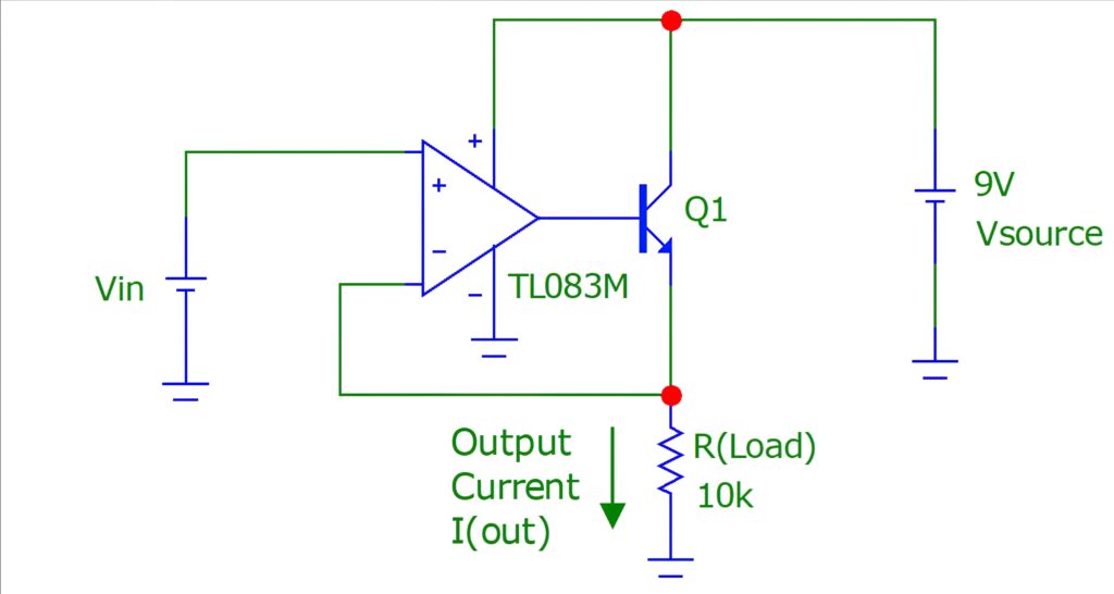
We will use a simple yet well-known voltage-to-current converter circuit (Figure 1) to establish the impact of any DC power supply changes on its output. Vsource represents the DC power supply and Vin is the measured voltage signal received from the instrument. The current through R(Load) is the output current sent from the voltage-to-current converter circuit to the process interface hub.

Figure 1: A typical voltage-to-current converter circuit
When feeding it with stable power (Vsource), ideally the circuit should reflect the output current across R(Load) in correlation with the input voltage signal (Vin). This useful measurement range of the circuit is at its best between Vmin and Vmax, where Vmin is the minimum input voltage (Vin) that can be measured by the circuit and produce a correlated output current. Similarly, Vmax is the maximum input voltage that the circuit can produce correlated output current against. Hence, the useful Vin that the circuit can perform well at is between Vmin and Vmax. If Vin is below Vmin or above Vmax, the circuit’s output won’t be useful, because the generated output current is not in good correlation with the input voltage; hence, we can call Vmin to Vmax the “useful input range”.
In this experiment, we monitor the useful input voltage span and output current generated by the circuit at various power supply voltages (Vsource). To do so:
- The power supply voltage and input voltage are tested between 1Vdc and 9Vdc.
- The temperature of the circuit is kept constant, to eliminate any temperature-related impacts on circuit performance.
Impacts
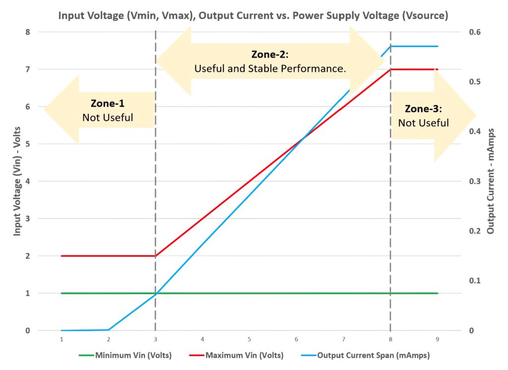
The minimum and maximum measurable input voltages are measured at every change in power supply voltage (Vsource). Then the measurable input voltage span (Vmax-Vmin) is calculated from the collected values. The circuit performance can be divided into three zones by plotting this data; see Figure 2. The graph has two Y axes, one for input voltages (left) and one for output current (right).

Figure 2: Input voltage (Vmin, Vmax), output current vs. power supply voltage (Vsource)
Zone 1:
This zone covers the range when the power supply voltage is below 3Vdc. In this zone the circuit shows output current that is not in good correlation with the input voltage. Also, the span of the useful and measurable input voltage is saturated at 1Vdc only. Thus, this zone is not useful for operating the circuit. This also means that the power supply voltage has to be above 3Vdc all the times.
Zone 2:
This zone covers the power supply voltage range between 3Vdc and 8Vdc. Here, the circuit shows a stable performance, with output current that is in good correlation with the input voltage. It is recommended that the circuit operates in this zone.
Zone 3:
This zone covers the case where the power supply voltage is above 8Vdc. Figure 2 shows that, when the power supply voltage is above 8Vdc, the output current is saturated at less than 0.6mA, hindering the output current in being in correlation with the applied input voltage. Therefore, it is not useful to operate the circuit within this zone, either.
As an electronics circuit designer, you must pay good attention to the stability of the voltage-to-current converter circuit with regards to its supply voltage. Ignoring this important concern could result in control system misbehaviour.


