The interest in wide bandgap devices such as gallium nitride (GaN) FETS and silicon carbide (SiC) FETs has increased in the industrial power market space in recent years. Because of their dramatically reduced charge characteristics, GaN devices offer high power densities at higher switching frequencies that would create tremendous thermal losses in MOSFETs operating at the same conditions.
Modern power supplies
GaN is widely used in modern power supplies to replace traditional silicon-based components. The technology enables significantly smaller, lighter and more efficient power adapters and power supply units (PSUs) by allowing faster switching speeds, higher power density and lower energy losses, especially as heat.
The interest in how these devices perform has led to a corresponding need to accurately simulate various GaN devices to optimise application performance. LTspice includes IC models of ADI’s latest DC-to-DC controllers that are optimised to drive GaN FETs. This enables design engineers to determine which GaN FET is best suited to their particular application and try various combinations for the best performance.
A common frustration users experience is choosing a FET device when product availability and selection from multiple vendors changes faster than the software can update the native component library. This leaves the user responsible for library management of custom symbols and devices. This can be a time-consuming distraction from the goal of finding an ideal solution for a particular application. Additionally, collaboration can be hampered when everyone on a design team does not have component libraries synced.
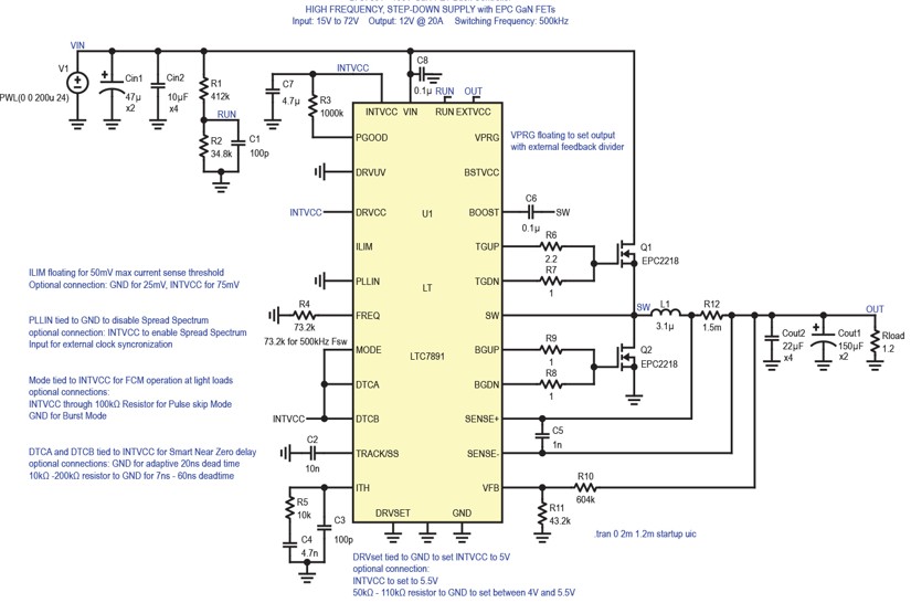
Examples of such portable circuits with GaN FET devices are available now on the product landing pages on analog.com. As shown in the Figure, an LTC7891 is configured for 12V, 240W operation using a pair of EPC2218 GaN FETs. This file can be downloaded and run directly without any device library changes at all. The feature that makes it self-contained and portable is that the GaN FETs used in the simulation are referenced as a subcircuit model. The symbols used are standard NMOS type symbols, which any LTspice installation always has, and each of them has been configured to point to the .sub directive statement with the same model name.
If the designer wishes to evaluate a different model, the process is simple and leaves the LTspice file every bit as portable for evaluation by any other team member as when it was downloaded. If additional devices are placed, the process is the same.
Working with LT Spice
To begin, a model library file (typically provided by the vendor) is needed to extract the model data. For easy reference, this web location is included on all example circuits provided on the power product landing page.
To demonstrate the process, the EPC2218A device is selected as the example. The downloads from most vendors usually come with several files. Also included are the symbol file and example file. We are interested in the library file.
If this is opened directly, a default library installer opens, which is not the preferred method. The goal is not to have to add more component symbols and devices to a local library that must then be managed. Instead, we will use the data contained in the library files directly. Open this using any basic text editor tool (Notepad, etc.) in order to get the data without performing a library install.
The library file has a long list of subcircuit text models, all of which begin with .subckt [model name] and end with .ends. Using the native find function of your system, find the model desired for insertion into the SPICE circuit and copy everything from .subckt to .ends. In the editor, open a .sp SPICE statement box and then paste it into the statement box. It is often useful to shrink the size of the pasted text so it is less obtrusive in the overall drafting space.
Place or edit an existing standard NMOS symbol already in the drafting space to link to the pasted subcircuit model text. To accomplish this, press control and right-click on the NMOS symbol. A properties table appears, and several key attribute changes must now be made.
First, the Prefix attribute needs to be changed to x. This forces LTspice to look locally for a model and the .subkt invocation with the desired name is used instead. Next, change the Value attribute to exactly match the model name directly after the .subkt in the first line of the pasted text. The InstName attribute may optionally be changed to whatever preference the user has (Q, G, etc.); the default is NM, but these are not NMOS FETs once configured to GaN devices.
The final detail to make the model fully operational in the SPICE file is to ensure the net order convention of the pasted model text matches the order of the standard NMOS device included in LTspice.
The standard NMOS model lists ‘Drainin Gatein Sourcein’ as the convention for the pin number on the NMOS device. Some models provided by GaN vendors vary from this with their included symbols and models. Innoscience, for example, uses ‘Gate Drain Source’, whilst EPC uses ‘Gatein Drainin Sourcein’.
Regardless of how the name or net order is listed by the provider, this can be made to match the LTspice convention by simply reordering the pasted text to match the ‘Drainin Gatein Sourcein’ convention. Since the included subcircuit method outlined here does not rely on using any symbols, devices, or model libraries, this re-ordering to match no longer matters. The file can be shared and opened by any copy of LTspice even if the local installation has default or modified libraries of the same device.
Finalising the design
The final step to any modification is to ensure that the model works properly as intended.
After running the completed simulation file, observe gate and switch waveforms to verify the simulation and provide a benchmark with which to compare actual measured waveforms. It’s important to remember that simulations – however accurate the models are – are only tools to save time, prevent costly mistakes, and lend insight into how the actual hardware functions. Gathering data from working hardware is always the ultimate verification of simulation results.
Compare the results from the evaluation board for the LTC7891 with the evaluation SPICE simulation for switch rising and falling. The overall dead time is fairly accurate, but parasitic elements of the actual hardware and measurement tools are not present in the simulation.
This is why it is important to start with simulation and end with bench evaluation. The gate resistors cannot be optimised in LTspice without an accurate model for the parasitic elements created by the PCB traces. This can only be achieved with careful measurement techniques on actual hardware to finalise the design. Importing the GaN model is the first step in this process.
Shared files
Using GaN device models in LTspice from any component manufacturer that provides them can be simple and avoid library management hassles if the method suggested in this article is employed. This allows the circuit designer to focus on the accurate simulation of devices, instead of the frustrations associated with symbol, device and library management.
Files created using this method can be repeated and shared by anyone using LTspice, and proving out design concepts with GaN-based power conversion is now the focus of the end user.
By James R. Staley, Senior Manager, Power Product Applications, Analog Devices