Simplicity and efficiency are one of the goals for most all designers. Here we will explore the design prototype of a simple yet efficient active balancing system for battery management systems (BMS).
In a BMS, multiple individual cells are typically connected in series to form a high voltage battery pack. This high voltage battery pack is the supply for various systems, including electric vehicles, high voltage energy storage systems, and uninterruptible power supplies. In these series-connected cells, the ideal operating condition is that all individual cells have consistent parameters such as cell voltage, internal impedance, state of charge (SoC), state of health (SoH) and operating temperature.
In reality, when a batch of brand new cells is first produced by the manufacturer, their performance and specifications are generally consistent. However, after being put into actual use, as the cells age, inevitable differences in performance arise due to factors such as load, environmental temperature and humidity, and the number of charge cycles.
When the performance differences between cells are small, they typically do not threaten the normal operation of the battery pack and do not require special attention. But once the performance differences between them become significant enough to threaten the proper functioning of the battery pack, it is crucial to address this issue. We will refer to these performance differences between cells as cell mismatch.
Cell capacity mismatch
As shown in Figure 1, if a few cells in a battery pack have significantly lower capacity than the others, they are referred to as weak cells. They can be problematic during both charging and discharging. During charging, a weak cell will reach full voltage more quickly and become fully charged ahead of the others. However, because the cells are connected in series as part of a larger battery pack, the charging current does not automatically stop once the weak cell is full. As a result, the entire battery pack’s charging process must be halted as soon as the weak cell reaches full charge, to avoid the risk of overcharging, which could endanger both the weak cell and the entire battery pack.
Similarly, during discharging, the weak cell’s voltage will drop faster, and it will reach its fully discharged state sooner than the rest. Again, the discharge process of the entire battery pack must stop immediately once the weak cell is fully discharged, or it risks being over-discharged, which also poses safety concerns. Observant readers may quickly realise that in a battery pack containing weak cells, the overall capacity utilisation is significantly reduced. Without cell balancing, healthy cells are unable to be fully charged or fully discharged during each cycle. Over time, as the cell undergoes repeated charge and discharge cycles, the weak cell – being subjected to more cycles – tends to experience faster capacity degradation, which worsens the mismatch with other healthy cells.
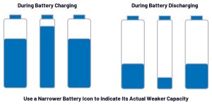
Figure 1: Impact of capacity-mismatched cells during battery pack charging and discharging
Cell impedance mismatch
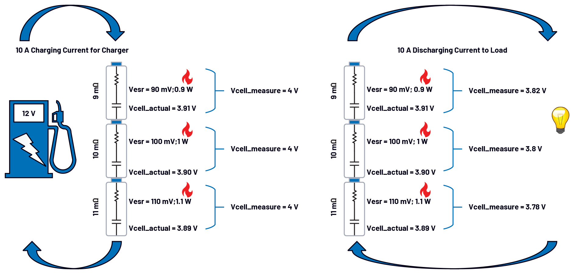
Apart from cell capacity, another important parameter of great concern is cell impedance. Similar to capacity mismatch, impedance mismatch occurs when a cell within a pack exhibits significantly different impedance compared to others. Some engineers use the electrochemical impedance spectroscopy method to measure each cell’s impedance and assess its health status. A healthy or relatively new cell typically has lower impedance, whereas an ageing or unhealthy cell tends to have higher impedance; see Figure 2.
If a particular cell within the pack has significantly higher impedance than others, it is referred to as an unhealthy cell for ease of discussion. Figure 2 shows this phenomenon by representing the cell as a simplified circuit model with a capacitor and a resistor in series during charging and discharging. It is important to note that this abstraction is a necessary simplification for discussion purposes in this article; while suitable for illustrating impedance mismatch effects, it does not represent the actual physical and electrical characteristics of a real cell.
During charging, an unhealthy cell with higher internal impedance experiences a greater voltage drop under a given charging current. In this case, if all cells exhibit the same voltage value, the unhealthy cell will actually store less energy. As shown in the figure, the unhealthy cell has a smaller Vcell_actual value during charging. Additionally, due to the higher power loss caused by its impedance, the unhealthy cell typically experiences a higher charging temperature.
During discharging, a higher impedance results in a greater voltage drop and higher power dissipation under a given discharge current. Consequently, the unhealthy cell experiences a more rapid decline in voltage and capacity and generally operates at a higher discharge temperature. Over time, with repeated charge-discharge cycles, the higher temperature and ageing effects further accelerate impedance increase in the unhealthy cell, exacerbating the impedance mismatch issue within the battery pack.

Figure 2: Impact of impedance-mismatched cells during battery pack charging and discharging
By analysing both capacity mismatch and impedance mismatch, you will notice that, although these two mismatches represent different aspects of cell imbalance, their ultimate effects are quite similar. Whether it is a weak cell with lower capacity or an unhealthy cell with higher impedance, both issues primarily impact the usable capacity and operating voltage of the battery pack. In a battery pack with weak or unhealthy cells, the overall capacity utilisation and safe operating time are significantly reduced. Moreover, these mismatched cells pose a continuous threat to the safety and normal operation of the well-performing cells within the pack.
The critical importance of passive/active balancing
Passive balancing is a dissipative method that typically operates during the charging cycle. Since weak cells have lower capacity, their voltage rises faster under the same charging current. When they reach or approach full charge first, the excess energy must be immediately dissipated. Although this energy dissipation leads to heat generation and thermal management challenges, it extends the charging time for healthy cells, ultimately improving the overall run time of the battery pack. Passive balancing is widely adopted in BMS, with most cell monitoring ICs already integrating this functionality.
Active balancing, on the other hand, transfers energy between cells using transformers, capacitors and inductors. This method works during both charging and discharging cycles, redistributing charge efficiently. While both passive and active balancing have their advantages and disadvantages, the choice of balancing method in practical BMS design is not simply based on a direct comparison of their pros and cons. Instead, it depends on the capacity and scale of the battery system.
Generally, the balancing current is set to about 1-5% of the cell capacity. For example, in a 4Ah lithium cell, if the balancing charge is 5% of its capacity, then 200mAh needs to be equalised. This scenario is well suited for passive balancing, where a BMS designer can implement a 200mA passive balancing circuit to dissipate the charge in about an hour or a 100mA circuit to do so in two hours. Ultimately, the designer can tailor the passive balancing strategy based on the passive balancing current capability of the selected cell monitor IC and the cell capacity.
In contrast, consider a 300Ah high capacity energy storage cell where the balancing charge at 5% reaches 15Ah. Even with a 300mA passive balancing current – which is already quite high – it would take over 50 hours to complete balancing. In reality, this time would be even longer, as continuous passive balancing on a single cell channel for extended periods could overheat and may damage the BMS chip. Therefore, active balancing is essential for high capacity cells.
For instance, if an active balancing circuit can handle 15A of charge transfer, the 15Ah imbalance can be corrected in about an hour. With 7.5A capacity, it would take about two hours, and so on. Unlike passive balancing, active balancing does not waste energy but rather redistributes it to other cells or packs, improving overall energy efficiency while easing the thermal management burden of the BMS.
By Frank Zhang, Applications Engineer, Analog Devices