By Lars Foerster, DC/DC Business Development Manager EMEA, TDK-Lambda
There are many benefits to using standard off-the-shelf DC-DC converters. They reduce design time, risk and cost often associated with discrete converters. For optimum operation and performance, however, a standard converter usually requires additional external components. Simple yet comprehensive instructions on which parts to use should be available in the manufacturer’s installation manual. It should also give guidance on where to position the components to achieve the best possible performance. It is highly recommended to draw a schematic first, then build and test the prototype before starting layout onto the PCB.
There are a few commonly used external components for standard converters:
Input capacitor
A low ESR electrolytic capacitor, positioned as close to the converter as possible, will minimise the impedance of the input wiring from the DC source to the converter. Ensure that the capacitor’s voltage rating is sufficient. Another point to consider is whether the end equipment will be used in below-zero temperatures. If it is likely that the capacitor will drop below -10°C, then its capacitance value may need increasing to compensate for the drop in its ESR.
Input fuse
The installation manual or datasheet will instruct whether an external fuse is required or not. If a fuse is necessary, then the rating and type will be recommended. Failing to follow these instructions may result in a safety hazard should the converter fail short-circuit.
Reverse polarity protection
If the converter’s input polarity could be reversed, a protective diode must be inserted across the input; see Figure 1. The diode needs to be rated for the maximum input voltage and, of course, have a higher surge rating than the input fuse.

Figure 1: Input connection to a standard DC-DC converter
Output filter
Fitting an electrolytic and/or ceramic capacitor across the positive and negative output terminals will improve the converter’s response to sudden load changes. This addition will also reduce the output ripple and noise, and compensate for impedance in the wiring or PCB traces between the DC-DC converter and the load.
To avoid any start-up issues, follow the maximum capacitance values specified by the manufacturer.
Output voltage adjustment
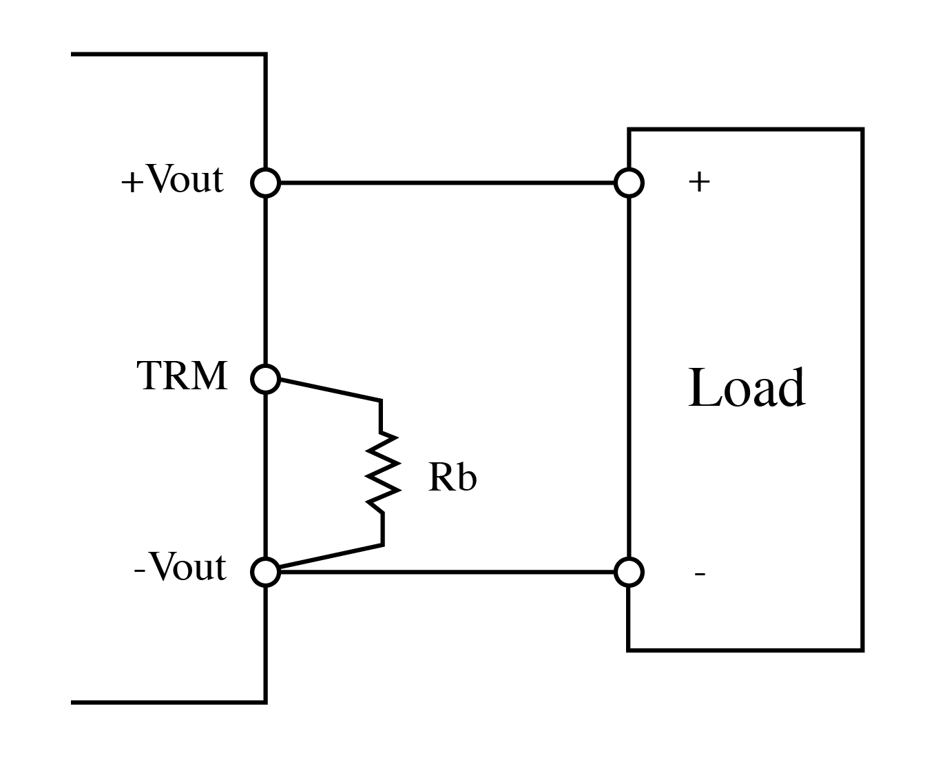
The DC-DC converter may feature a ‘trim’ connection if the output voltage is adjustable; see Figure 2.

Figure 2: Adjusting the DC-DC converters output using the ‘trim’ connection
To trim up the output voltage, connect a resistor from the ‘trim’ connection to -Vout. Be sure not to exceed the maximum output power of the DC-DC converter. To trim the output down, the resistor is connected to the +Vout. To avoid noise pick-up, ensure the trim resistor is located as close to the DC-DC converter as possible. The manufacturer should provide the relevant equations to calculate the required resistance.
Remote on/off
Most DC-DC converters offer a function to turn the output on or off remotely, using a relay, switch or resistor; see Figure 3.

Figure 3: On/Off control using the remote control (RC) terminal
As there are two types of remote on/off polarity, care must be taken. For ‘negative logic’, the RC terminal must be pulled down (shorted) to -Vin to activate the output voltage or pulled high (disconnected) to inhibit the output. On the other hand, ‘positive logic’ requires the RC terminal to be open to enable, or shorted to -Vin to inhibit.
If the installation manual does not provide enough details, try contacting the manufacturer’s sales or technical support office.