By Tim Paasch-Colberg, Product Management Oscilloscopes, Rohde & Schwarz
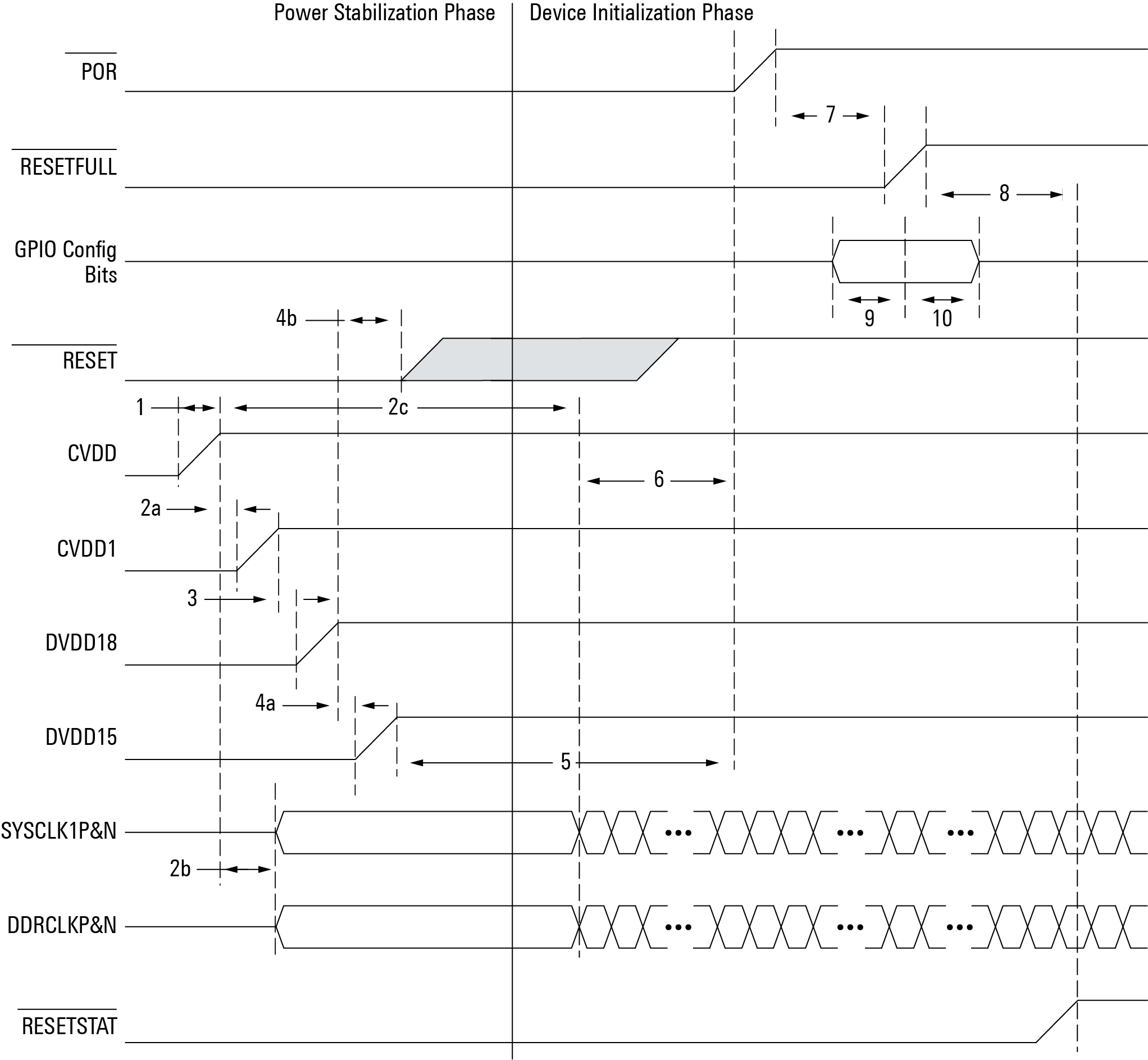
Components such as FPGAs, CPUs and DSPs usually must meet very specific requirements relating to the order in which their supply voltages are powered – a process known as power sequencing. There’s a power-up sequence and its reverse, the power-down sequence, which is also a recommended process – but not always!
During circuit design, it is important to capture and analyse the characteristics of multiple voltages for these devices during power-up and power-down, as well as during voltage interruptions. If powering up/down voltages is done in the wrong order, it could lead to components damage.
Equally, voltages must not exceed manufacturer-specified tolerances and, in many cases, they must also comply with defined slew rates, specific delays upon reaching a target value, and ramp-up times. During power-up, it is also necessary to minimise current draw and ensure that I/Os are at high impedance.
Right test equipment
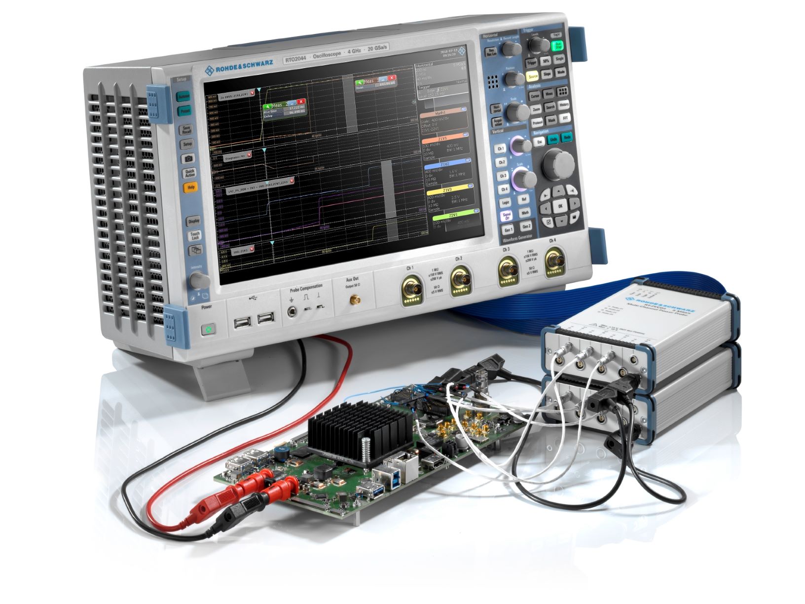
To verify correct power sequencing, circuit designers need the right tools, one of which is as an oscilloscope with a suitable probe. Typical requirements for a multichannel oscilloscope probe specify up to four voltage and four current channels with a very high dynamic range. Ideally, each channel should have an ADC-bit resolution at 5Msample/s and 1MHz bandwidth. Using two such probes on a four-channel oscilloscope allows a parallel analysis of up to 20 voltages. Current channels must be operated as highly-sensitive voltmeters in external shunt mode.
The choice of compatible oscilloscope depends on the test requirements – measured values, accuracy requirements, and a number of data points and analyses, as well as the test environment – design, development, production, and so on.
Applications such as embedded design development and analysis of power electronics components can be well within the capabilities of a cost-effective, Windows-based oscilloscope with the appropriate functions. A full-featured multi-domain test solution for fast debugging of complex electronic circuits provides bandwidths from 200MHz to 2GHz and comprehensive time, frequency, protocol and logic analysis functions. Acquisition rate in excess of one million waveforms per second, combined with deep memory of up to 200Msamples, helps developers rapidly isolate even rare or random errors.
More demanding tasks such as power integrity measurements require laboratory oscilloscopes, ideally with bandwidths to 6GHz. The latest generation of instruments in this class also support testing of radio interfaces on 802.11ac WLAN components for IoT modules in the 5GHz band, and of high-speed communications interfaces such as USB 3.1 with data rates of 5Gbit/s. With multi-domain capability, developers can investigate complex and challenging components and modules in a short time. Furthermore, synchronised results from time, frequency, and protocol and logic analysis enable system-orientated, highly-focused debugging with acquisition rate around one million waveforms per second.
Advanced analysis
To verify power-up and power-down sequences of FPGAs, CPUs and DSPs, a primary requirement is to characterise the start-up and shutdown behaviour of their supply voltages, with defined delays that range from a few nanoseconds to several milliseconds.
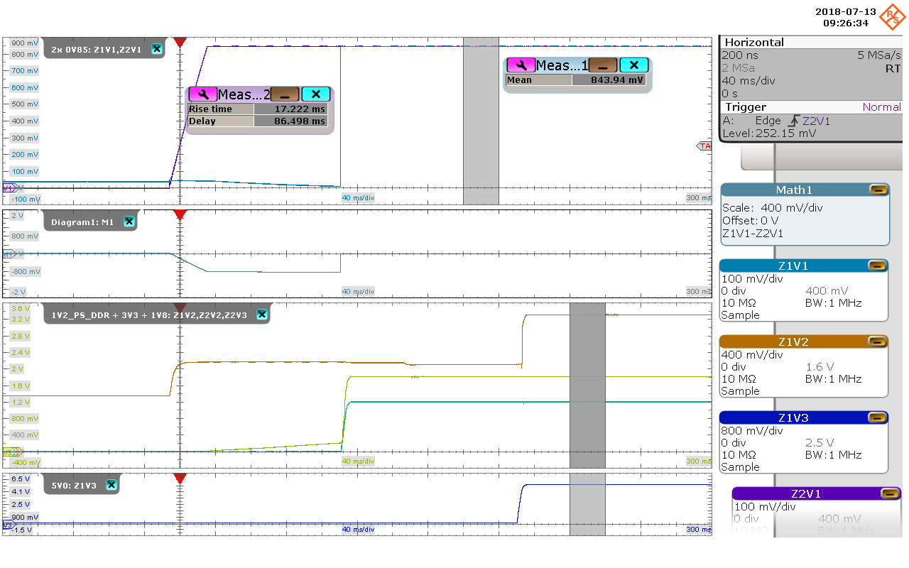
For measuring voltage ramp-up times, slew rate is an important metric. Levels of the different supply voltages of FPGAs, CPUs and DSPs are usually between 1V and 5V. This, together with recommended minimum and maximum ramp-up times that range from a few microseconds to several milliseconds, means that recommended slew rates should range from a few V/μs to several V/ms. Last but not least of these requirements is to verify the differences between supply voltages. During ramp-up the measured difference between the various voltages should not exceed defined values.
Specific supply voltage characteristics can be analysed using the measurement and math functions integrated in today’s advanced oscilloscopes. On-screen cursors make it quick and easy to perform manual analysis of multiple parameters, such as the delay between different channels. Oscilloscopes with sampling rates of 5Msample/s or better make it possible to measure typical slew rates of several volts per millisecond. More sophisticated analyses, such as required voltage difference between channels, benefit from maths functions for individual oscilloscope channels.
Over and above power sequencing, stable and clean power rail voltages are a crucial requirement for adequate performance of almost any electronic design. This is especially important as designs strive to minimise power consumption and increase battery life. Consequently, power rail voltages and their tolerance windows are generally on a downward trend. This calls for test instrumentation that combines suitable sensitivity and high accuracy. Today’s devices require measurement accuracy of 0.1% for voltage and 0.2 % for current – at least 10 times higher than most standard oscilloscope channels can deliver, but well within the capability of advanced cost-effective instruments. Test instrumentation is available now to support user-friendly measurement of delay, ripple, noise and ramp-up time on individual channels, in order to verify power sequencing accuracy and correctness.
This includes multichannel power probes like the R&S RT-ZVC, which are ideal for verifying power sequencing – not least owing to their high accuracy. In addition to verifying the power-up/power-down sequences of supply voltages, such probes can also analyse the voltages, determining absolute voltage values.
Designed for measuring currents and voltages with high resolution, such probes support another important application besides power sequencing, i.e. current consumption measurements on Internet of Things (IoT) devices, where current drain plays a key role.