The peak detector circuit is a simple yet versatile circuit, used to detect the peak value of an input signal. In its simplest form it consists of a diode and a capacitor, and it can be used in many applications, including radio communication, audio signal processing and power supply monitoring. The diode clamps the input signal to a positive voltage, which means the capacitor will only charge when the input signal is above a certain threshold. The capacitor stores the signal’s peak value; the output of the circuit is a DC voltage that represents the input signal’s peak value.
Applications
The peak detector circuit is a non-linear circuit, which means that its output is not a linear function of the input – which can be disadvantageous in some applications.
This circuit is suitable for detecting peak amplitudes of an audio signal, useful for normalising the signal, or for compression or limiting. The circuit can also be used to demodulate a radio signal or for automatic gain control. In power supplies, the peak detector can monitor the peak voltage, to protect from overvoltage conditions.
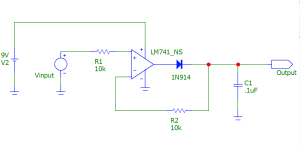
Figure 1 shows a simple peak detector circuit, which consists of an op-amp, two resistors and a capacitor. Here we will try to determine how the circuit behaves at various input signal frequencies.

Figure 1: A typical peak detector circuit
Experiment setup
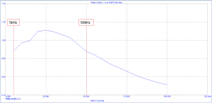
The input signal to the circuit for our experiment is 1V DC, with the input frequency varied from 5kHz to 100kHz in 5kHz increments. The output signal’s amplitude was measured at each step, and plotted; see Figure 2.
For the experiment, we assumed the following:
- All circuit components were kept unchanged.
- The ambient temperature is static at 25o
- The power supply voltage is kept at 9Vdc.

Figure 2: Output signal amplitude vs. input signal frequency
From Figure 2 we can determine the following:
Unstable performance
The peak detector circuit does not deliver a stable output voltage, similar to the input signal voltage. The output voltage only matches the input voltage at momentarily, at a specific frequency. For example, when the input signal is at 5kHz or 50kHz, the output voltage will match it. However, any slight change in the input signal voltage will rise of lower the output voltage compared to the input.
Amplification effect:
When the input signal frequency is between 5kHz and 50kHz, the peak detector circuit delivers an output signal with a magnitude higher than that of the input signal. This amplification effect is clearly seen in Figure 2; it is at its highest when the input signal frequency is 25kHz.
Attenuation affect:
In contrast to the amplification effect, the peak detector circuit delivers an output voltage lower than the input signal when the input signal’s frequency is above 50kHz. The output signal amplitude is reduced exponentially, as seen in Figure 2.
Based on these results, it can be concluded that this peak detection circuit can’t deliver a stable output voltage when the input signal frequency changes. The output signal is similar to the input only at specific input frequencies, 5kHz and 50kHz. This makes the circuit’s use limited to applications where the input signal frequency is very stable.
Also, the circuit amplifies and attenuates the input signal based on the input frequency: it amplifies it when the frequency is between 5kHz and 50kHz, but attenuates it when it rises above that level.
These findings are very important for electronic circuit designers to know, since they must be fully aware of this circuit’s amplification and attenuation effects at various input frequencies. It is also important to be aware of this circuit’s frequency instability when the input signal frequency is not fixed.
By Dr Sulaiman Algharbi Alsayed, Managing Director, Smart PCB Solutions


