As efficiency targets for power converters get more demanding, the focus is turning to magnetic components to improve power density and reduce losses.
Great strides have already been made over the years in improving the efficiency of power converters thanks to latest semiconductor technologies, where wide band-gap devices used in resonant converter topologies allow single-stage efficiencies of over 99%. With a steady reduction in semiconductor static and dynamic losses, attention is increasingly diverted to the heat dissipation from passive components – particularly magnetics.
Better packaging and heat dissipation
One of the desired benefits of higher converter efficiency is smaller, lighter and lower-cost heatsinking and packaging. However, to match this, magnetics in the form of energy storage inductors, filters and transformers must also reduce in size, typically facilitated by increasing the switching frequency. Filter and storage inductors passing net DC generally require less inductance as switching frequency rises, which can allow smaller cores and fewer winding turns for the same flux density. This produces little or no increase in total magnetic component losses if the AC component of the current is small.
For transformers, core size can also reduce with increasing frequency for the same number of winding turns and flux density. However, because transformer current is all AC, eddy current and core hysteresis losses also rise substantially with rising frequency. Additionally, semiconductor dynamic losses increase with frequency, so there is always a trade-off between system frequency, efficiency, temperature rise and size.
Transformers can nevertheless be very efficient and losses are often disregarded at medium and low power and low frequencies. At higher power, however, even fractions of a percent of inefficiency can result in significant power loss, with correspondingly high average and hot-spot transformer temperatures. This can be problematic, especially if the advantage of small magnetics size has been realised by increasing the frequency, giving an overall small transformer surface area for heat dissipation. High temperatures can damage insulation and risk safety or, at best, force the use of unnecessarily high-temperature ratings of wire insulation and bobbins to achieve agency safety certification. Ohmic resistance of copper windings also increases with temperature, leading to further losses and, in turn, higher temperatures still.
An approach to minimise temperature rise in transformers is to provide controlled paths for the heat to be led away. Ferrite cores used at high frequency have relatively poor thermal conductivity, typically 2-5W/mK compared with 400W/mK for copper, so temperature differentials across ferrite can be high, effectively thermally insulating the interior of a transformer. Thick windings of a few turns such those found in a planar construction can be used to lead heat away, but the approach is not effective for inner windings which may often be high voltage primaries with relatively large number of turns of thinner wire.
A new approach
Murata has recently made advances with winding arrangements for high-power, high-frequency transformers with its patented PDQP technology, which interleaves windings in a novel way, minimising leakage inductance and skin and proximity effects. The PDQP technique decreases losses, but a further technique patented by Murata embedding heatsink plates within the core and winding structure provides better control of internal transformer temperatures. The method suits high-power transformers where temperature rises might be high and the core is typically assembled from combinations of U or U and I cores. Figure 1 shows the general approach, and, here, eight cores U7-U8 make up the assembly with sandwiched metallic heatsink plates shown in blue and red.

Figure 1: Murata patented transformer heatsinking arrangement using embedded metal plates
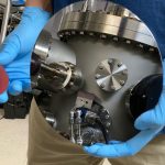
Figure 2 shows the internal construction, in this case using 12 U cores, with the top six removed for clarity. The central thicker plate acts as a conduit for heat and can be mechanically attached or bonded to an external housing or ‘cold wall’ to provide heat sinking for the assembly’s interior. The thinner plates in red can be bonded to the central plate or can protrude from the assembly for attachment to the external thermal sink. The whole assembly can be bonded or clamped together, but the pressure and small separations are not critical, except for the faces between the top and bottom U core sets. All other interfaces are not in the magnetic field path, and small gaps are not material, although thermal coupling is better with closer contact.
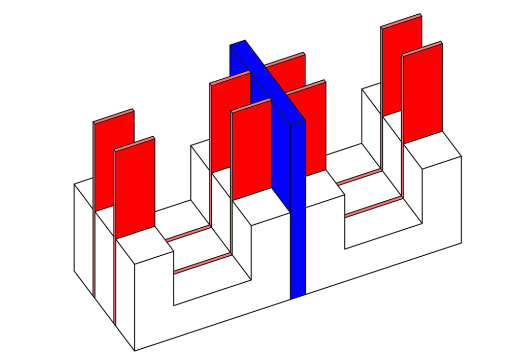
Figure 2: Internal construction of Murata’s new transformer heatsink approach
Similar to steel laminations in 50/60Hz transformers, the thin plates in red do not form complete conducting loops and eddy currents would anyway be primarily induced through the plate’s thin dimension. Eddy current is proportional to the area of the induced current loop and power lost is proportional to the square of the current, so both are minimised by thin plates.
The central, thicker plate in theory has no eddy currents if symmetrical with the windings, as the magnetic field from each core aperture cancels. Material for the plates can be copper for highest performance, or aluminium for cost-sensitive applications. The thermal conductivity of copper is better than aluminium by a factor of two, but its electrical conductivity is higher by a similar ratio, so any residual eddy currents would produce lower losses in aluminium.
Practical results
To confirm the performance of this approach to transformer heatsinking, a 50kW 24kHz converter was simulated with embedded plates, and compared with a version without them. An actual transformer was then constructed and loaded, and temperature measurements taken. The converter is typical of an EV battery charger with a 700VDC input bus and an output of 417V at 122A.
Figure 3 (left) is a simulated temperature map of the transformer with included heatsink plates (external view), whereas the image on the right shows a cross-section of the part with internal hot spots. The ambient temperature was set at 31°C, and a maximum internal temperature of 56.2°C is indicated – a rise of around 25°C.

Figure 3: Temperature rise simulation with transformer-embedded heatsinking
The same transformer was simulated without additional heatsinking; Figure 4 shows the two equivalent plots, where an internal maximum temperature rise of 39°C can be clearly seen – 50% higher than that with heatsink plates. Note that the temperature scaling is different between Figures 3 and 4.
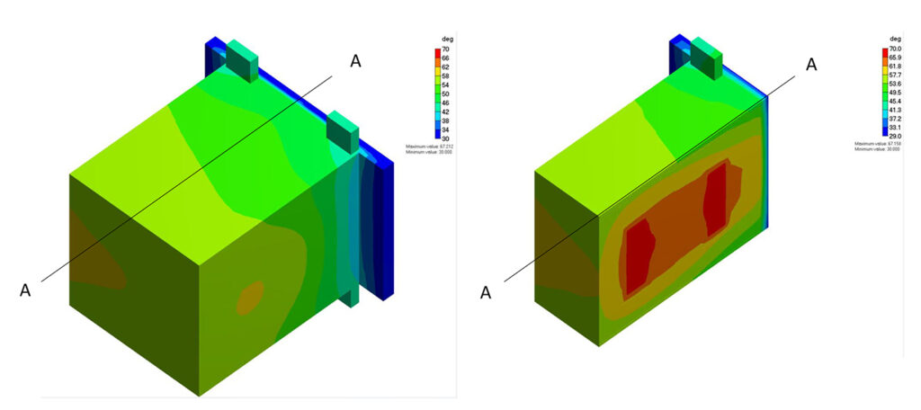
Figure 4: Temperature rise simulation without transformer-embedded heatsinking
Measured internal temperatures of a working transformer with heatsink plates are shown in Figure 5, with embedded thermocouples recording a maximum internal hot-spot temperature of a little over 58°C, within 1.5°C of the simulation.
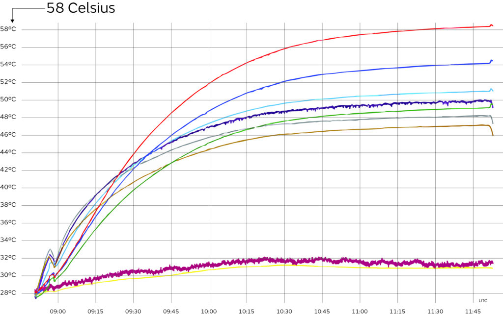
Figure 5: Measured internal temperatures of a working transformer with heatsink plates
This Murata transformer heatsink approach promises higher power from a given transformer assembly or lower temperature for the same power with a corresponding increase in reliability and lifetime. Safety margin to the material temperature limits is improved, and agency certification is facilitated without necessarily resorting to specialised and expensive high-temperature insulation systems. A combination of simulation and practical measurements confirms the value of the approach.
By Andrea Polti, Global Product Manager – Magnetics, Murata