By Tom Gregory, Product Manager, 6SigmaET
Power electronics are designed for high-powered applications, often found in the automotive, railway or aerospace industries. For very high-power applications, > 500A IGBT devices are used for switching and control – devices designed for efficiency. However, even with very high efficiencies, they still dissipate a significant amount of heat.
Devices operating at high temperatures may fail, have long-term reliability issues and reduced efficiency, and could be a safety risk. Any thermal management device must fit within the constraints of the system, including its weight, cost, size and other parameters. Additionally, cooling systems must be highly reliable.
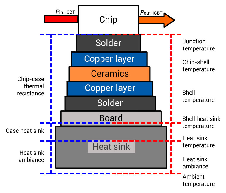
Engineers designing power electronics need to ensure that heat generated in the IGBT devices can be transferred away as easily as possible, into a heat sink or liquid-cooled cold-plate. As shown in Figure 1, heat transfers from transistors through the package materials, solder to the board and the board itself to the heat sink; the thermal resistance of a material determines how easily heat transfers through it. Therefore, material selection is crucial in power electronics design: to ensure materials have low thermal resistance (high thermal conductivity), low electrical conductivity where they need to insulate, and, also, they shouldn’t expand or contract too much during temperature changes.

Figure 1: IGBT typical thermal stack up
The load on power electronics devices is typically transient in nature, which, over time, has an impact on both the immediate performance of a semiconductor and its lifespan. Power cycling – where a device rapidly switches between high and low power loads causing large swings in temperature – can stress the solder and bonding of semiconductor devices, resulting in device failure.
In addition to material selection, it is important to consider the thermal resistance when heat is transferred between two touching materials, called contact resistance. The interface between two materials is normally poor because, at microscopic level, the surface is not smooth and there are many air gaps, and still air has a very high thermal resistance. The more changes in material, the higher the overall thermal resistance will be between the power electronics device and the heat sink or cold plate.

Figure 2: Air gap difference for direct contact and using a thermal interface material (TIM)
Thermal interface materials (TIMs) such as thermal greases or pastes are used to improve contact resistance. Air has a thermal conductivity of 0.026W/mK at 20°C ambient temperature. A thermal grease usually provides up to 10W/mK and thus conducts 400 times better than air. Manufacturers offer many different options for TIMs depending on the application.
Looking at PCBs, they are typically made of FR4, a type of fibreglass. However, for many power electronics applications, FR4 cannot withstand the high temperatures generated, and FR4 doesn’t have high enough thermal conductivity to transfer heat away effectively. Typically, ceramic- or aluminium-based boards are used in high-powered applications. Then a fan and heat sink, or a liquid-cooling system can extract the heat away. Cost, reliability and performance factors influence the choice of cooling method.
To deliver a fully optimised product, these decisions need to be tackled as early in the design process as possible. Unfortunately, many designers still rely on ‘rules of thumb’ to deal with thermal complications, which leads to over-engineering products, or trying to “manage out” thermal complications at the back end of their projects. Indeed, according to research from 6SigmaET, only 25% of design engineers test any thermal operation early on in their designs, while 27% wait until after a design is complete.
Using simulation to solve at all levels
Through the use of thermal simulation, engineers can test the thermal performance of power electronics before they are manufactured – including the precise detail of the IGBT device as well as the entire thermal management system.
By creating a thermal simulation model in advance, engineers can test their designs using a wide variety of different materials; for example, switching from copper to aluminium at the click of a button. Simulation also enables designs to be tested in a large array of different environments, temperatures and states. This will not only help identify potential inefficiencies, but also reduces the need for multiple real-world prototypes, further helping to lower overall costs.
Thermal simulation software allows engineers to quickly create a thermal model of their system, allowing parts to be imported from CAD packages or to define parts such as cold plates and heat sinks. To accurately predict device temperature, simulation software calculates airflow and heat transfer by conduction, convection and radiation using Computation Fluid Dynamics (CFD). Thanks to improvements in both software and hardware, simulations can be done at very fine resolution, using hundreds of millions of grid cells, guaranteeing most accurate predictions.
6SigmaET
Tools like 6SigmaET are making it increasingly easy for engineers to understand the precise thermal challenges of their designs. This means that thermal considerations can be dealt with far earlier in the design process, enabling the thermal performance of power electronics semiconductors and systems to be fully optimised, reducing reliance on expensive late-stage fixes and avoiding unnecessary over-engineering.
Put simply, the ease of use and capabilities of today’s thermal simulation tools means there is no longer any excuse to rely on ‘rules of thumb’ when it comes to the thermal performance of semiconductors in power electronics products.


