By Dr. Dogan Ibrahim, Professor at the Near East University, Cyprus
Laboratories are an important and integral part of all university engineering courses. Students put into practise the complex theory they have learned in their lectures, and this gives them the chance to apply the theory to real-world projects.
Circuit theory is a core subject and is a fundamental part of all electrical and electronic engineering courses. In conventional laboratory experiments, it is required to purchase electronic components and instruments and use them to build circuits and then carry out experiments using these circuits. Although physical laboratory experiments are very useful, they have some problems associated with them:
- The purchase of electronic components and instruments are usually costly. A large number of similar components and instruments are usually required for a group of students doing the same experiments and this can be very costly.
- It is well known that the characteristics of electronic components change with ageing and temperature and this can result in unexpected errors in experiments.
- Physical instruments can easily be damaged, for example by dropping them. Similarly, components can be damaged by applying large voltages across them.
- It may not always be possible to find the required components, and students may have to wait for long times before they can build their projects.
- High voltages can cause electric shock; students are required to observe and follow the laboratory safety rules. An instructor should be present to give guidance and check students’ circuits before power is applied.
- Laboratory instruments need periodic calibration and this can be costly, too. Also, the instruments are not available during the calibration process.
As an alternative to using physical instruments and components, most engineering laboratories nowadays offer computer simulation of circuits. A simulator is basically a computer program that simulates the behaviour of a real circuit. A simulator includes accurate software models of instruments and components. Students pick the required components and virtual instruments and join them to form the required circuit. The simulation is then started which displays the circuit behaviour in terms of AC and DC analysis, transient response, noise response, and so on. Using a simulator instead of physical components has the following advantages:
- The components and virtual instruments are computer programs and therefore there are no cost issues.
- Any electronic component can easily be modelled with a simulator. As a result, there is no need to purchase components or to wait for the delivery of components.
- Since the virtual instruments and components used in a simulator are programs, they cannot be damaged, for example by connecting them wrongly or by applying high voltages across them.
- There are no calibration problems associated with the virtual instruments and, as a result, the instruments are available at all times with the same specifications.
- The voltages and current in all parts of a circuit can easily be measured using a simulator.
- There is no concept of component ageing with the simulation.
- The circuit configuration (e.g. the components) can easily be changed in simulation at no cost
- Simulation can be used in distant engineering courses where students can carry out experiments in their own times and at their own places of study.
Simulation also has some important disadvantages that the students should be aware of:
- Because there are no component tolerances or ageing problems in simulation, students may get the idea that all components are ideal in real world.
- Simulation hides some important concepts from students. For example, passing large currents through a resistor can overheat and damage the resistor and this cannot be observed in a simulation.
There are many commercially-available professional circuit simulators in the market. Some educational establishments or private individuals also offer simulators free of charge that can be downloaded from Internet. Some currently-available popular circuit simulators are: Proteus, TINA, PSPICE, SiMetrix, CircuitLab, LTspice, Multisim, Micro-Cap, PLECS, CircuitLogix, and many others.
In this article we shall be looking at the basic features and specifications of the popular TINA simulation package. An example circuit simulation will also be presented – simulation of a simple electronic transistor amplifier circuit.
The TINA simulator
TINA is a professional integrated computer simulation program including schematic circuit design, analogue and digital circuit simulation, PCB design, filter design, RF circuit design, microcontroller system design, equation editor, logic design, and other useful electronic design and simulation tools. The TINA software package has been developed by DesignSoft (www.tina.com), and the software is called The Complete Electronic Lab. One of the nice features of TINA is that the simulated circuit can easily be implemented on a PCB with auto-placement and auto-routing capabilities. Students can also use the Gerber plotting and CNC drilling options of TINA to learn and design and implement a prototype of their projects. The latest version of TINA is v12.1. It is distributed in several forms to meet the needs of various individuals and companies. It is available as a Professional or as an Academic package. The package has the following options depending on the price and the features:
- Industrial version
- Educational version
- Classic version
- Basic Plus version
- Basic version.
The Industrial version includes all of TINA’s features and is the most expensive. The Educational version is slightly cheaper and the features such as the transient noise analysis, stress analysis are not available and the Verilog lines are limited. The Classic version is similar to the Educational version, but some of the features, such as the S-parameter analysis, the model maker and Network analysis are removed.
Basic Plus and Basic versions are similar to the Classic version, but the number of nodes are limited, and Verilog simulation is not available. The Academic package consists of the Student version, and the Educational version. The student version is similar to the Educational version, but the number of pads and nodes are limited to 100.
TINA supports two real multifunction PC instruments produced by DesignSoft called TINALab II and LabXplorer. With the help of these instruments students can interface real hardware to TINA simulation package and observe the results on the oscilloscope, use signal analyzers, multimeters and function generators in real time. The function generator can generate sine, square, ramp, triangle, and arbitrary waveforms from DC to 50MHz, with logarithmic and linear sweeps. Arbitrary waveforms can be programmed using TINA’s easy-to-use built-in interpreter language. Both TINALab, LabXplorer and may other instruments can be interfaced with TINA through LabVIEW from National Instruments.
An online version of TINA, called the TINACloud, is also available from DesignSoft that enables TINA software to run in a browser without any installation – and anywhere in the world. TINACloud is useful in distance education as it includes online tools for testing students’ knowledge and monitoring their progress. TINACloud is included free of charge for one year in all TINA distributions.
Example circuit using TINA
A single-stage common-emitter transistor amplifier is considered as an example here. Figure 1 shows the amplifier circuit diagram, drawn using the Schematic Editor of TINA. A BC107A-type NPN transistor is used in this design. The output of the amplifier is denoted as Out:1 and it can be connected to various instruments to measure or observe the signal.
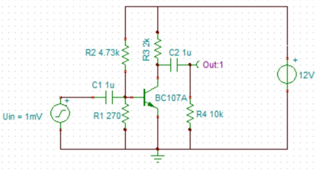
Figure 1: Single-stage common-emitter amplifier
After starting the simulation, the output voltage is displayed (Figure 2) on a virtual multimeter and is shown to be 152.64mV.
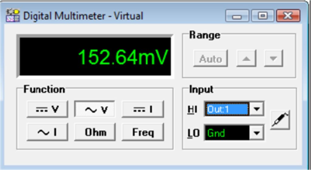
Figure 2: Output voltage displayed on virtual multimeter
The output waveform on the virtual oscilloscope is shown in Figure 3. The frequency response of the amplifier is shown in Figure 4 using the virtual signal analyser instrument.
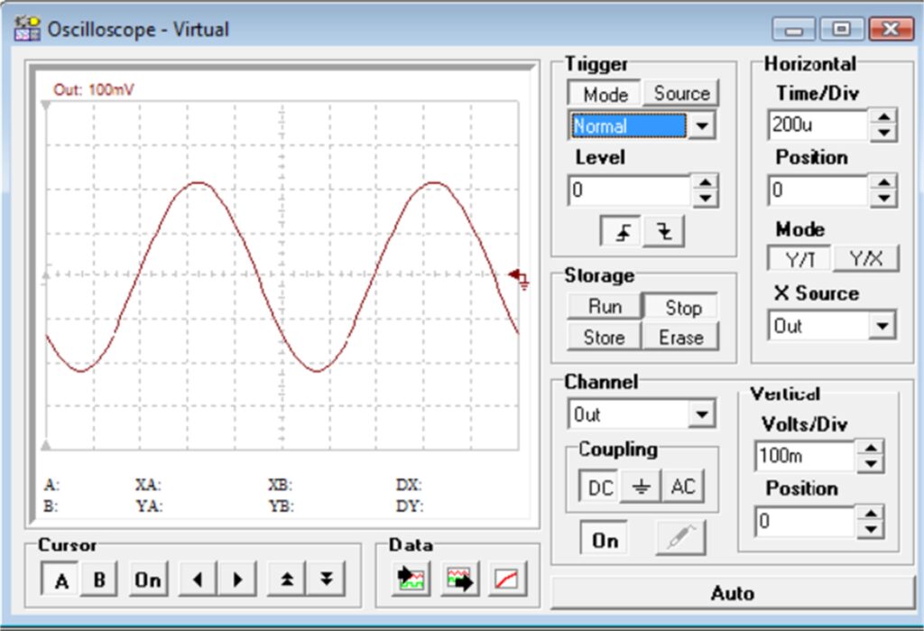
Figure 3: Output waveform on virtual oscilloscope
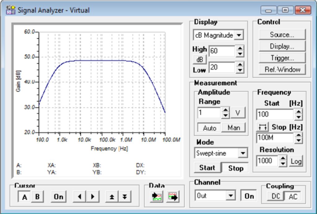
Figure 4: Frequency response of the amplifier
The voltage at any node of the circuit can be displayed by clicking at the required node. For example, as shown in Figure 5, the DC voltage at the base of the transistor is displayed as 641.6mV.

Figure 5: The DC voltage at the base of the transistor
It is also possible to display the AC and DC voltages and currents at all parts of the circuit in the form of a table. Figure 6 shows the circuit with the nodes labelled automatically. The DC voltages and currents are shown in Figure7.

Figure 6: Showing the nodes in the circuit
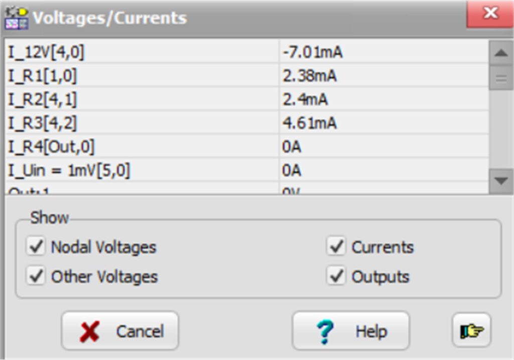
Figure 7: Table of DC voltages and currents in the circuit
The transient response of an amplifier circuit is important, since it can show if there are any non-linearities in the output response. Figure 8 shows the transient analysis of the circuit where the output is 180º out of phase with the input, and there are no non-linearities. The Fourier spectrum of an amplifier shows the frequency elements in its output response and is useful to find out if there are any harmonics present. This Fourier spectrum for the amplifier circuit used in this example is shown in Figure 9. As can be seen from this figure, the fundamental frequency is at 1kHz, which is the frequency of the input waveform.

Figure 8: Transient response of the circuit
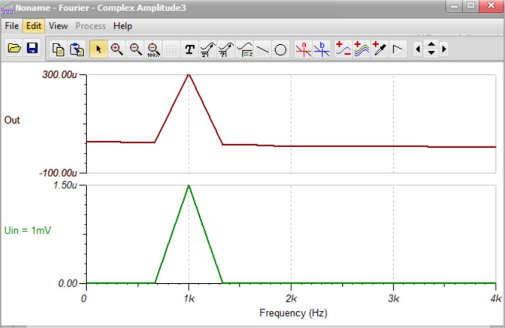
Figure 9: Fourier amplitude spectrum of the amplifier
TINA also offers the option to display the circuit schematic in 3D as shown in Figure 10.
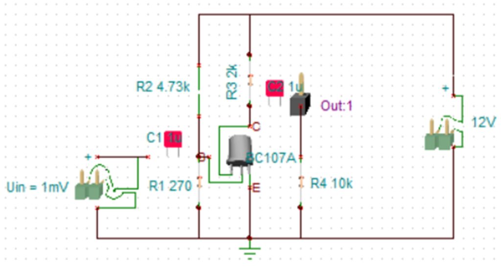
Figure 10: Circuit displayed in 3D
PCB Design
After the circuit has been designed and the user is satisfied with the simulation results, the next stage is usually to build the physical circuit on a breadboard and make sure that it works as expected. After this stage the user may wish to design a PCB layout of the circuit and have some prototype PCBs made for the circuit. This is easily done in TINA by clicking the PCB Design button in the Schematic Editor where the screen changes to PCB design.
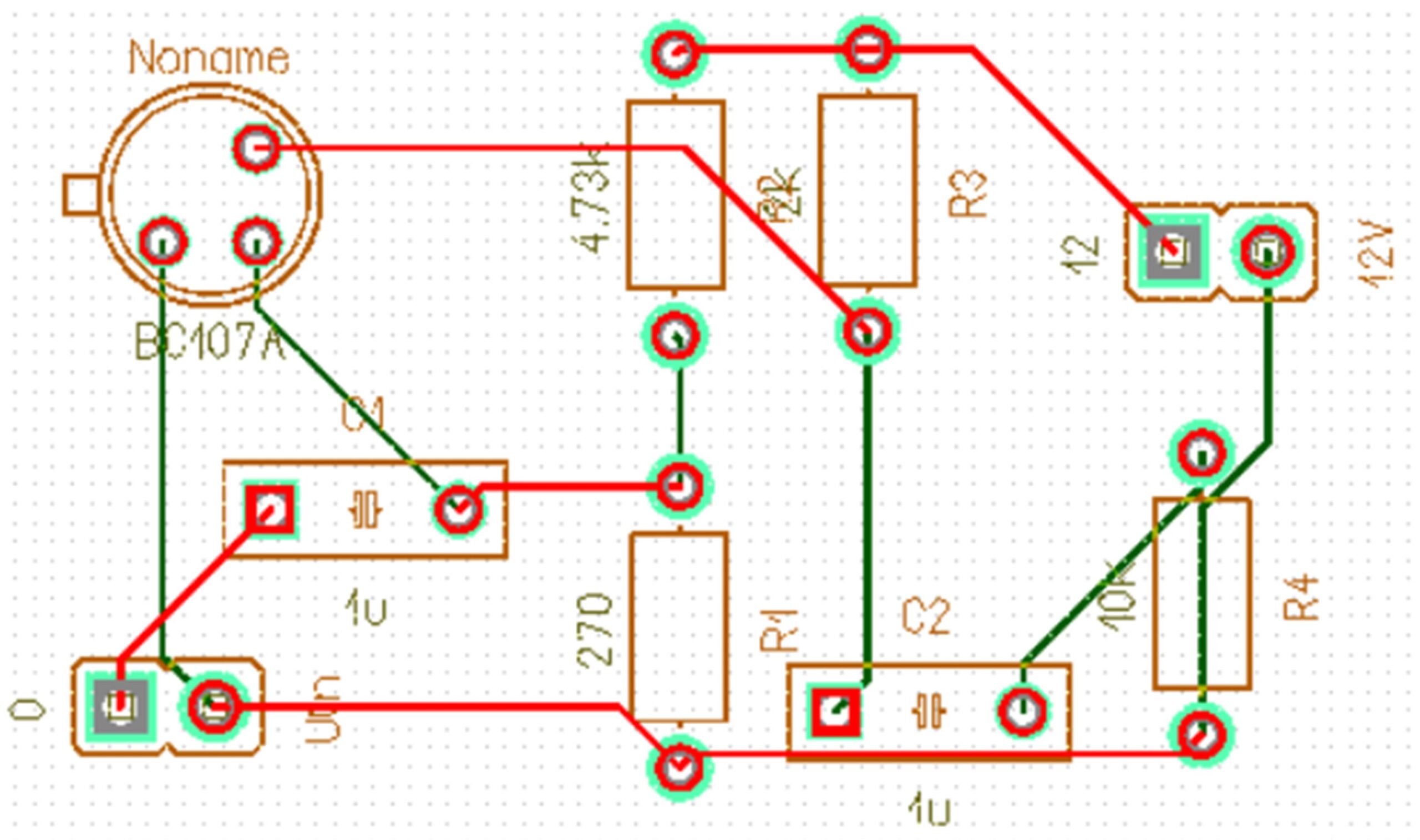
Figure 11 shows the PCB layout of our amplifier. The user has the option of configuring all the PCB parameters such as the track width, track to track size, track to via size, track type, inserting text, etc. The user also has the option to auto-place the layout, to auto-route, to set the layer colours, to create a Gerber file of the PCB, to create a NC drilling file, and so on.
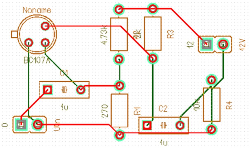
Figure 11: PCB layout of the amplifier
The user can also display the complete design in 3D at different angle of views as shown in Figures 12 and 13.

Figure 12: Design in 3D (side view)
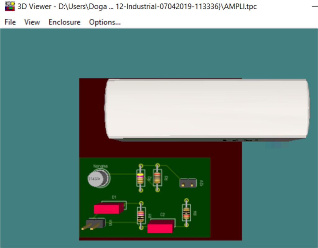
Figure 13: Design in 3D (top view)
The bill of materials is a list of all the components used in the circuit and is useful for cost analysis. This can easily be displayed by clicking File -> Bill of Materials, as shown in Figure 14.
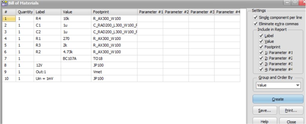
Figure 14: Bill of materials list
TINA offers the features that the schematic design or netlist can be exported to other manufacturers’ format (e.g. Altium, OrCAD, etc as shown in Figure 15). Users can save schematic designs in TINA as Altium Projects from the File, Export menu point.
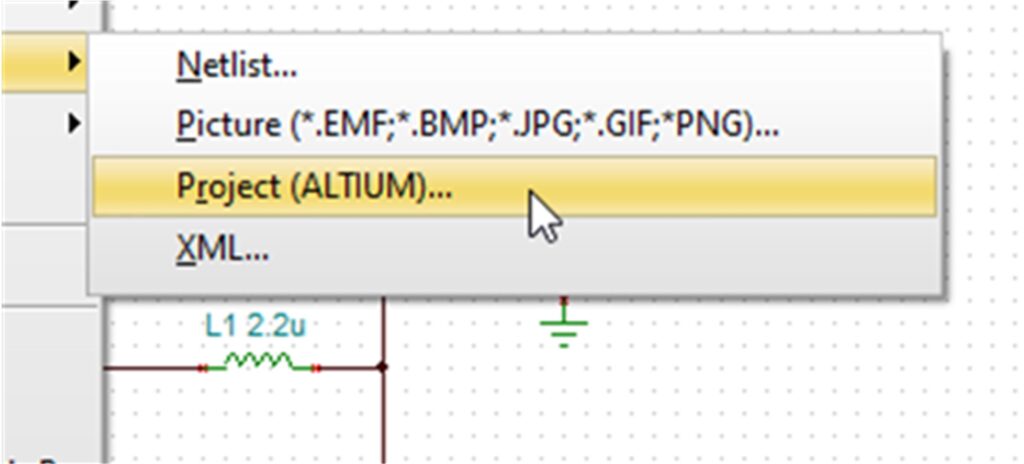
Figure 15: The exported projects can be opened by Altium Designer
The Altium PCB project or native OrCAD netlist can be imported into OrCAD Capture. Similarly, in OrCAD Capture, the user can click File -> Import -> Altium Schematic Translator to launch Altium-Capture translator to import TINA generated project.
Figure 16 shows the Net List of the amplifier circuit designed in this paper in the form of a Pspice text file.
AMPLI (TINA Netlist Editor format)
**************************************
** This file was created by TINA **
** www.tina.com **
** (c) DesignSoft, Inc. **
** www.designsoftware.com **
**************************************
.TEMP 27
.DC LIN V12V 0 1 50M
.AC DEC 166 100 100MEG
.TRAN 3N 3M
.OPTIONS ABSTOL=1U ITL1=100 ITL4=10
.PROBE V([Out])
V12V 4 0 12
VUin 5 0 DC 0 AC 1 0
+ SIN( 0 1M 1K 0 0 0 )
QNoname 2 1 0 Q_BC107A_N_1
C2 2 Out 1U IC=2.531903
R4 Out 0 10K
R3 4 2 2K
R1 1 0 270
R2 4 1 4.73K
C1 5 1 1U IC=-642.203492M
.MODEL Q_BC107A_N_1 NPN( BF=180 BR=1 IS=76.77F RB=10 RC=0
+ CJC=6.019P VJC=750M MJC=330M TR=10N CJE=10.65P
+ VJE=750M MJE=330M TF=510.2P EG=1.11 VAF=100
+ XTB=2M KF=0 AF=1 )
.END
Figure 16: Netlist of the amplifier
Tina packages
In this article we have looked at some of the features of the TINA simulation package. In addition to simulating digital and analogue circuits, TINA can be used to simulate microcontroller-based systems with processors such as 8051, Arduino, PIC18, PIC24, PIC32, STM32, TI Tiva etc. The author recommends the Student version of TINA to all electrical and electronic engineering students. The cost of the off line Student version was only €49 (perpetual license) and only €12/year at the time of preparing this article.

