By Mike Horton, CTO, and Dan Dempsey, Senior Director, Automotive Business Development, Aceinna
Fully-autonomous Level-4 and Level-5 vehicles are getting a lot of attention at the moment, with some test fleets already running in the US. However, the more immediate promise of Level 2+ and Level-3 automated driving solutions are far more realistic because of the price and technical advancements.
The Society of Automotive Engineers Automation Levels defines the automation levels from 0 (no automation) to 5 (full automation) such that a Level-0 car has no autonomy and the driver must perform all driving tasks, whereas a full-automation Level-5 vehicle performs all driving tasks, in all conditions; see Figure 1. Between Level 0 and Level 5 is a continuous advancement of driving capabilities enabled by more advanced sensor and electronic systems.
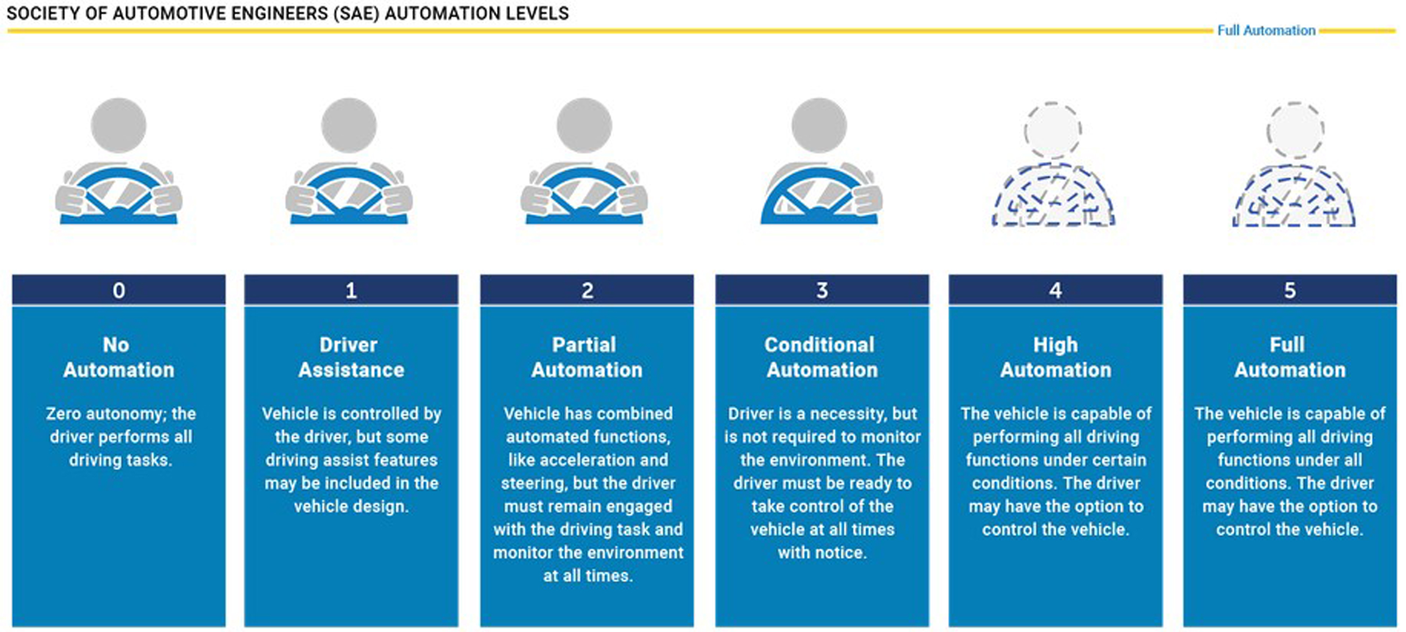
Figure 1: The Society of Automotive Engineers Automation Levels chart
In-Between Levels
Level-1 vehicles will be driven by a person but will include some assistance features like collision avoidance or lane-departure warning. Vehicles with Level-2 partial-automation systems combine more advanced electronics that control acceleration and steering functions, often referred to as adaptive cruise-control and lane-keep assist, already found in vehicles such as Tesla, Nissan, Daimler and Volvo. Level-2 systems require the driver be alert at all times and be able to take over control of the vehicle when necessary.
An unofficial Level 2+ system is already available, with complete acceleration, braking and steering control, and the driver monitoring the environment and being engaged and willing to take over control. For example, the GM SuperCruise system used on some Cadillac cars is identified as a Level-2+ solution.
Level 3, or conditional-automation systems control acceleration, braking and steering under certain conditions and do not require drivers to monitor the environment. Audi first introduced a Level-3 solution in 2017 on its premium A8 models.
Vehicles with Level-4 systems are able to perform 100% of the driving functions under certain conditions in limited areas. Waymo’s cars in Arizona fit this description as they operate in warm, mostly-dry weather conditions and only on roads in a geo-fenced area.
Sensors Galore
As the automation levels increase from 1 through to 5, the sensors and electronic systems become more sophisticated and more integrated. A basic Level-1 function, like collision avoidance, can be accomplished with an intelligent radar or camera module that detects an object, determines its position, and communicates with a car’s braking system to slow down the vehicle in an emergency. It is a relatively simple system that performs a limited function.
A Level-3 vehicle, on the other hand, requires data from radar, camera, ultra-sonic, LIDAR and GPS/IMU sensors be fed into a central computing module that fuses it all and structures it within an HD map. This requires a complete integration of sensor data to make decisions for acceleration, braking and steering as a human driver would.
Level-4 and Level-5 solutions expand the operating range of the vehicle, needing better sensors and drastically increased computing power to detect, comprehend and execute driving functions in even the most unexpected conditions. While the Level 4/5 systems are being developed, Level-2/2+/3 systems are already on the road and promise to relieve much of the tedium and frustration of driving that occurs on our over-congested roads.
Accurate Navigation
A critical element to Level-2 and Level-3 systems is a highly-precise navigation solution that includes an accurate GNSS/GPS receiver with local correction coupled to a precision Inertial Measurement Unit (IMU) to operate when the GNSS/GPS signals are unavailable. The GNSS/GPS receiver correction system must deliver accuracies of < 10cm to keep the car in the correct lane. The more accurate the IMU, the more time the GNSS/GPS receiver has to recover a lost signal before the position confidence falls below an acceptable level.
Usually, the IMU errors need to stay in the cm level range for 5s, 10s, or even longer, depending on the interrupt mechanism, bridges, tunnels, urban canyons, or tree canopies. When the position confidence falls below an acceptable level, the system warns the driver and hands over control.
To highlight the importance of robustness in such a system, imagine a left-hand turn in the downtown of a major city like Chicago; see Figure 2. Left-hand turns are particularly challenging because the car must turn across an intersection and enter the right half of the intended street. Due to the 90o orthogonal-angle of the intended road, the car’s camera and LIDAR sensors may not have visibility of the upcoming road, lane markers or obstructions. Additionally, the GNSS/GPS signal is frequently interrupted in urban canyons because of line-of-site blockage by tall buildings and reception of errant reflected signals. In this common case, camera, LIDAR and GNSS/GPS signals are all temporarily invalid and the IMU must determine the car’s position and direction. A tightly-coupled GNSS/IMU is a requirement to eliminate signal interruption and ensure a turn is accurately and safely negotiated.

Figure 2: Left-hand turn in urban canyon can interrupt GPS/GNSS, camera and LIDAR signals
IMU Advantages
The GNSS/GPS receiver uses primary signals from the GNSS/GPS satellite constellation that continuously beams down signals to receivers that perform calculations to determine a vehicle’s position. To obtain accuracy less than 10cm, a satellite or ground-based correction network must also be used to adjust for timing and atmospheric distortions inherent to the GNSS/GPS network. Because the signals come from space, they can be interrupted by physical structures that block the transmission path.
The advantage of using an IMU is that it does not require any external signals or inputs, since it senses its own attitude based entirely on the physical forces that act on it. It is very accurate in measuring acceleration and rotational rates, so it calculates an object’s position and velocity with high accuracy. However, the position and accuracy measurements accumulate errors over time, the GNSS/GPS signals are used periodically to correct for any absolute positioning errors. The GNSS/GPS receiver can determine a vehicle’s absolute position in space when signals are available, and an IMU can measure the vehicle’s movement and estimate its position and velocity when the GNSS/GPS signal is not available. When fused together, the two systems provide precise positioning under most conditions.]
OpenIMU from Aceinna
A new robust hardware and open-source software stack called OpenIMU from Aceinna provide a reliable navigation solution. The platform simplifies and modernises navigation system development through a robust, professional-grade, customisable open-source software stack and easy-to-integrate hardware.

Figure 3: The OpenIMU full-stack solution
By using OpenIMU, the system developer can start immediately (before purchasing hardware) by, first, running simulations and, then, by modifying existing, well-tested algorithms in the OpenIMU distribution. In addition to having runnable source code and a simulation environment, full documentation, including all the math of the algorithms, is available online.
On the embedded-development side, the OpenIMU tool chain is an easily-installed extension to the popular open-source code editor Visual Studio Code. Simply install VS Code and search to install the Aceinna extension. Once installed, the OpenIMU home page will appear and a new navigation project can begin.
The easiest way to get started is to import a Custom IMU example. These examples are ready-to-use OpenIMU applications which demonstrate different levels of navigation algorithm complexity.

Figure 4: OpenIMU platform home page
Of course, just simulation and coding will not drive the car, since hardware’s needed, too. Applications built with the OpenIMU stack run directly on reliable OpenIMU hardware, the first of which is the OpenIMU300 module; see Figure 5. This is a reliable nine-Axis IMU module that is fully-calibrated in Aceinna’s factory for errors over temperature. The OpenIMU300 is also calibrated on a three-axis rate-table to reduce errors like non-linearity and misalignment by up to a factor of 10x over other low-cost IMUs.

Figure 5: OpenIMU300 inertial measurement unit module
The OpenIMU300 also features multiple serial ports for integrating external GPS and other types of sensors, an SPI port and a powerful 168MHz Coretex M4 floating-point CPU. The baseline OpenIMU300 typically delivers drift better than 6o/hr.
The solution has real-world collection and data logging. A combination of Python scripts and a developer’s website called “Aceinna Navigation Studio” make collecting and analysing data easy; there’s no need to write a custom driver for your new algorithm. A configurable JSON file allows these data logging and graphing tools to work even when your OpenIMU application has customised the data packet/messages to your own unique requirements.
Aceinna is working on higher-performance modules with several packaging options now. A developer’s kit comes with a JTAG pod, evaluation board and a precision text fixture to help developers go from code to test in minutes.