By Rolf Horn, Application Engineer, Digi-Key
Brushless DC (BLDC) motors are increasingly used across many and varied applications, from remote IoT-controlled garage openers and car windows, to satellite propulsion controllers. The problem designers face with BLDC motors is that the control algorithms necessary to drive them are complex and often specialised, making them difficult to get them up and running in a reasonable amount of time. Developers are generally left to choose between a software-based solution running on a microcontroller, which provides flexibility but also puts a computation burden on the microcontroller, or use a dedicated IC, which could encapsulate the full BLDC motor control function and move BLDC control away from the host.
BLDC motors
BLDC motors provide efficient torque delivery over a wide range of speeds; they are also quiet and don’t suffer from mechanical friction like brush motors. BLDC motors are controlled by current, not voltage, making them suitable for a wide variety of applications and for which they come in a wide variety of shapes, sizes and costs.
For example, the Trinamic Motion Control’s QBL4208-41-04-006 is a 24V, 4000rpm motor that provides torque to 0.06Nm; see Figure 1. The motor is lightweight (0.662lb) and provides several options for controlling the motor, such as through sensorless operation using back electromotive force (BEMF), or built-in sensors that report the position.

Figure 1: The QBL4208-41-04-006 is a 24V, 4000rpm BLDC motor that can deliver a little over 0.06Nm of torque at maximum speed
For more torque, designers can use QBL4208-41-04-025 from Trinamic Motion Control (Figure 2), also a 24V, 4000rpm BLDC motor but delivers a little over 0.25Nm.

Figure 2: The Trinamic Motion Control QBL4208-41-04-025 is a 24V, 4000rpm BLDC motor but delivers a little over 0.25Nm of torque
BLDC motors are driven through three-phase lines that generate a magnetic field that pushes against permanent magnets to move the stator and spin the motor. In theory this sounds easy, but in practice driving a BLDC motor is fairly complicated, leaving developers to choose between a software framework to drive the motor or a dedicated chip.
Software versus dedicated ICs
There are several factors that developers should consider when choosing how to spin their BLDC motor:
- Bill of materials (BOM) versus labour costs;
- Board versus software complexity;
- Maintenance time and costs.
From a hardware perspective, it can be very tempting to take the software route because a dedicated chip can add costs to the BOM. Instead, some consider spending a fraction more on a microcontroller, and put all the control algorithms on it. Yet, despite appearances, this is not necessarily a winning situation, since there are some ramifications for this decision that the design teams should consider. Although it decreases the overall BOM, this solution places additional burden on the microcontroller to process the BLDC state data and continuously drive the motor. If the microcontroller is also handling other sensors and continues to communicate and control other devices, the software development and maintenance costs could go through the roof if care is not taken.
That said, a software-based solution does allow fine tuning the motor control algorithms.
As an example let’s consider a case of moving the motor control algorithm into the microcontroller, which could take up more RAM and flash memory. It does appear like it needs more consideration, but a microcontroller designed for motor control, like the Texas Instruments F280049CRSHSR, will have the algorithms built into its library that resides in the microcontroller ROM. Hence, the only additional code for the application are function calls to access the library, which does all the heavy lifting.
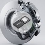
Spinning a BLDC motor doesn’t just come down to the software though, it also requires hardware. Figure 3 shows an example application using a C2000 microcontroller – of which the F280049CRSHSR is a family member, illustrating everything that is required and optional to drive a BLDC motor. Beyond a microcontroller, there also needs to be some 3-phase power stage that can drive the three phases of the BLDC motor to make it spin.

Figure 3: The Texas Instruments C2000 microcontrollers are designed for motor control applications. This image shows an example application with the microcontroller at the centre and the required and optional circuitry required to drive a BLDC motor
The Allegro MicroSystems A4964KJPTR-T motor driver
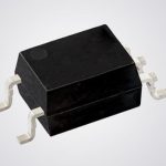
The Allegro MicroSystems A4964KJPTR-T motor driver chip is a dedicated BLDC motor driver that contains all the functions needed to drive a motor; see Figure 4. Specifically designed for automotive applications and for use with N-channel MOSFETs, the chip has sensorless start-up and commutation, so it requires a minimal amount of external hardware. It also operates over a wide range of voltages (5V5-50V), which covers nearly every standard application, along with automotive systems.
Perhaps its most interesting feature is that it can be interfaced to a microcontroller or central electronic control unit (ECU) over the serial peripheral interface (SPI) to configure the various registers for motor operation. Obviously, the microcontroller does not need to be as powerful as one that is running the motor control algorithms itself. Alternatively, the A4964KJPTR-T motor speed can also be driven without SPI, by simply providing a pulse width modulation (PWM) signal. There is non-volatile memory where the settings for the motor can be stored, which are loaded at power on, allowing just a PWM signal to control the motor.

Figure 4: The A4964KJPTR-T BLDC motor driver provides sensorless start-up and commutation. Motor speed can be configured through SPI or through a dedicated PWM signal
From a configuration perspective, the A4964KJPTR-T has 32 addressable 16-bit registers, plus a status register. The status register is unique in that the first five bits are transmitted during every read/write operation on the SPI, allowing the software to check a general status, to see if there are any faults or issues. All of the status registers can be read out during write operations to the chip since no data is being transmitted back from the A4964KJPTR-T.
In the 32 addressable registers, there are also two special registers: register 30 is write only and register 31 is read only. The ‘write only’ register allows a developer to set the demand input, or the duty cycle rate the motor will be driven at with a value between 0-1023. The ‘read only’ register data changes based on the requested data written to register 29 – the readback select register. This register allows a wide range of telemetry information to be retrieved such as:
- Diagnostics
- Motor speed
- Average supply current
- Supply voltage
- Chip temperature
- Demand input
- Applied bridge peak duty cycle
- Applied phase advance.
Beyond these special registers, the remaining 30 allow the specific motor application to be tuned and faults to be enabled or disabled, such as current limit and gate drive faults.
Dedicated motor drivers are interesting because they sum up everything that needs to be configured to run the motor into a few dozen configuration registers. This dramatically removes any software overhead that would otherwise exist on a microcontroller and, perhaps more importantly, can dramatically reduce software development and maintenance costs. Driving the BLDC is then nothing more than sending a PWM that can have no overhead in a microcontroller, or enabling the motor bit and providing an SPI-based demand input to spin the BLDC.
Using the A4964KJPTR-T
The A4964KJPTR-T is fairly straight forward to interface to, but there are several tips and ways to simplify and speed up its development:
- The status register is returned on the SPI interface during every write to the chip and is not available as a dedicated, addressable register. This means that driver code needs to monitor the SPI bus SDO line whilst writing to the chip to get status information.
- Fault information is included in the status register, but an overview of the chip status is available in every SPI transaction in the first five bits, when the microcontroller is providing the address access information. This data can be used to determine if any issues have occurred.
- There are two unique registers in the memory map that are read and write only. This is straight forward, but be careful not to try and read from the write only register, as this will write whatever dummy data is being used in the read sequence to the register.
- The chip has some non-volatile memory that can be used to store default parameters, which are loaded into RAM and used during start-up. To ensure that the chip boots into the ready state most efficiently, program “safe” start-up values into the chip.
- If the end device is working in a noisy or radiation-rich environment, it is not a bad idea to design the application code to reassert the configuration data periodically. The chip configuration is stored in RAM, which means that it is vulnerable to cosmic rays, bit flips and all those rare events that can happen with electronics.