As electricity use accelerates across industries, battery systems are becoming central to modern electronic design. Improvements in renewable energy generation, such as solar and wind, have made power production more efficient than ever. Yet the ability to generate electricity is only one part of the equation. Without effective ways to store that energy, much of it might go unused.
Engineers are increasingly being tasked with designing systems that not only generate power but also store and deliver it reliably. This shift has elevated the role of power management in battery-centric systems. Rather than acting as a simple subsystem, modern battery management architecture is now responsible for ensuring that energy storage technologies operate safely, efficiently and predictably. For lithium-based battery systems in particular, sophisticated monitoring and control mechanisms are essential. From managing voltage and temperature limits to balancing cells across large battery packs, these systems allow safe deployment of high-density energy storage in a wide range of applications.
Power management – central to battery performance
Lithium-based batteries have become the dominant chemistry in modern energy storage because of their ability to deliver high energy density and strong power output. Cells like lithium-ion, lithium-polymer and lithium iron phosphate are widely used in both consumer and industrial systems. However, these advantages come with strict operational requirements.
Lithium cells must be operated within specific electrical and thermal limits to avoid damage. A typical lithium-ion cell, for example, might operate from around 4.2V at full charge down to approximately 2.5V at the end of its safe discharge range. Charging or discharging outside of these limits can damage the internal chemistry and potentially lead to catastrophic failure.
Current draw must also remain within specified limits. A datasheet might specify that a cell be charged at a particular current level while allowing higher discharge currents during operation. Temperature management is equally critical because exceeding safe temperature thresholds can degrade the cell or trigger thermal events.
Considering these constraints, lithium batteries require careful monitoring and protection systems to maintain safe operation. This is where power management becomes essential.
Engineers must design systems capable of continuously monitoring battery conditions while regulating voltage, current and temperature throughout the life of the pack. Without these safeguards, the advantages of lithium-based energy storage would be difficult to harness safely.
Battery management system fundamentals
At the centre of modern battery power management is the battery management system (BMS). This electronic control architecture monitors individual battery cells, enforces safe operating limits and ensures balanced performance across the pack.
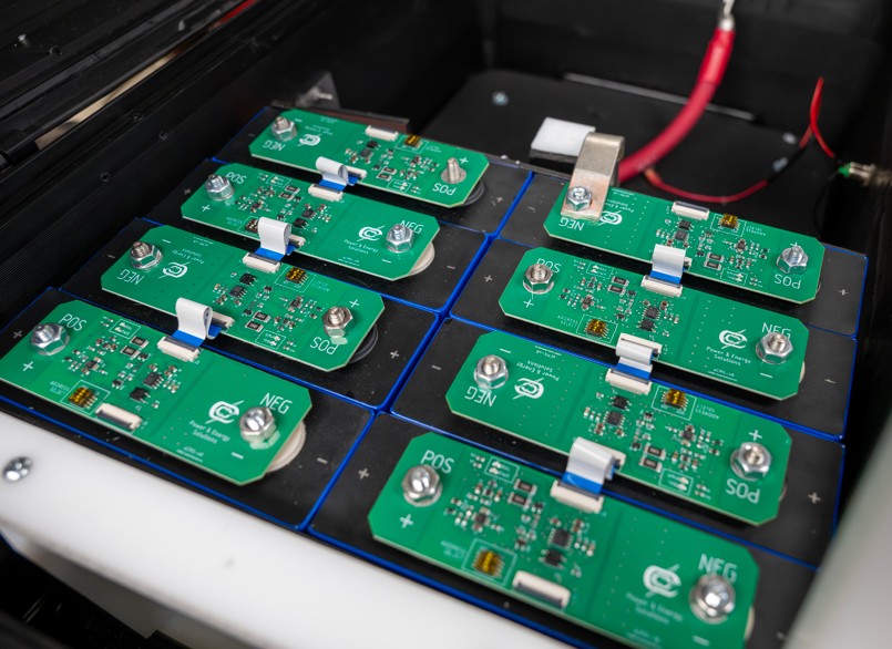
In many applications, multiple cells are connected in a series to achieve higher system voltages. For instance, a battery pack designed to deliver approximately 24V might be constructed from several cells that are connected positive-to-negative in sequence. Since individual lithium cells typically output around 3.6-3.7V nominally, multiple cells must be combined to reach the required system voltage. Within such series configurations, each cell must be monitored individually. Small differences in capacity or internal resistance can cause cells to drift apart in voltage over time. If left unmanaged, these imbalances can reduce system efficiency or push certain cells outside safe operating limits. To prevent this, the BMS continuously monitors the state of each cell.
Analogue front-end monitoring
A key component of many BMS architectures is the analogue front-end (AFE) integrated circuit (IC). The AFE measures the voltage of each individual cell or group of cells within the battery pack and often manages transistor gates used during balancing operations. It typically communicates measurement data to a microcontroller via an inter-integrated circuit (I²C) interface, allowing the microcontroller to assess and determine how the system should respond. This could be that balancing is required, charging should stop, or a fault condition has occurred.
Many AFEs also include inputs for temperature sensors and current sensing, along with a dedicated alert signal that can interrupt the microcontroller if a fault condition is detected. This ensures that safety-related events are handled immediately.
Supporting control electronics
Additional components are often included within a BMS to expand functionality and improve safety. For instance, a secondary protection IC might provide redundant monitoring in case the primary control system fails to respond to a fault condition. If abnormal behaviour persists, the secondary system can disconnect the battery pack by triggering a fuse or other cutoff mechanism.
Many battery packs also include a fuel-gauge IC, which estimates the battery’s state of charge. Because battery voltage changes non-linearly during discharge, determining remaining capacity requires complex modelling of the discharge curve. Dedicated fuel-gauge devices handle this calculation and report the remaining charge level to the system or user interface.
Power flow into and out of the battery pack is typically controlled using back-to-back MOSFETs, which allow the system to independently enable or disable charging and discharging paths. In higher-voltage systems, larger contactor relays may be used instead.
Together, these components create a layered control system capable of monitoring cell health and preventing unsafe operating conditions.
Cell balancing and pack stability
When cells are connected in a series, maintaining balance between them becomes one of the most important tasks of the BMS. Cells rarely behave identically over time. Small variations in manufacturing or usage conditions can cause one cell to charge or discharge slightly faster than another. Over repeated cycles, these differences accumulate.
If a single cell reaches the upper voltage limit while others remain partially charged, the pack can’t continue charging without risking damage to that cell. Conversely, a weak cell may reach its discharge limit early, reducing the usable capacity of the entire battery pack. Balancing circuits address this problem. Two primary approaches are used: passive balancing and active balancing:
Passive balancing dissipates excess energy from higher-voltage cells through resistors, releasing it as heat until all cells equalise. Although energy is lost in this process, passive balancing is widely used because it is relatively simple and inexpensive to implement.
By contrast, active balancing transfers energy from higher-voltage cells to lower-voltage cells. While more efficient, this method requires additional circuitry and complexity.
In many lithium-ion systems, balancing begins when cell voltages diverge by approximately 30-50mV. Since balancing usually occurs near the top of the charge cycle, the energy dissipated in passive systems is generally small relative to the total pack capacity.
Challenges in multi-cell systems
Designing a battery system involves more than simply combining cells. Engineers must carefully consider system architecture, electrical limits and communication strategies.
One of the first questions in any battery design project is the intended application. A system designed for high-power output will have very different requirements as compared to one designed primarily for energy storage. These decisions influence cell chemistry selection, pack configuration and BMS design.
As the number of cells increases, so too do the electrical challenges. Large battery packs might operate at high voltages, which can create differences in ground potential between subsystems. In such cases, communication links between battery modules might require electrical isolation.
High-current capability introduces additional design considerations. Multiple MOSFETs placed in parallel could be necessary to safely handle the current load, while protective devices such as fuses or circuit breakers are often used as a final safeguard against excessive current.
Another challenge arises from electrical noise. High-current switching can create noisy ground planes, which could interfere with sensitive measurement circuits. Designers must therefore carefully manage PCB layout to maintain clean reference signals for the control electronics.
Thermal management considerations
Temperature control is another key aspect of battery power management. Battery packs typically incorporate temperature sensors at multiple locations throughout the assembly. These sensors report temperature data to the BMS, which allows the system to detect overheating conditions and shut down the pack if necessary.
Balancing circuits can also generate heat, particularly in passive balancing systems where excess energy is dissipated through resistors. To prevent localised hotspots, many systems avoid balancing adjacent cells simultaneously.
Power electronics, such as MOSFETs, occasionally require additional cooling measures when handling high-current loads. In some cases, these components are mounted on heat sinks or supported by forced airflow.
Cell arrangement within the enclosure also plays an important role. Early battery designs often separated cells with insulating materials to reduce thermal interaction. Today, more advanced systems incorporate new approaches to temperature control, including liquid cooling methods, although these designs are still emerging in commercial products.
Even enclosure design can influence thermal performance. A completely sealed enclosure might trap heat and slow cooling times, potentially causing the battery pack to reach its temperature limits during sustained operation.
Validation, testing and certification
Before battery systems can reach the market, they must undergo extensive validation and certification testing. Battery packs are commonly subjected to high charge and discharge cycles to ensure the BMS responds correctly when operating conditions exceed safe limits.
Multiple certification bodies such as Underwriters Laboratory (UL) in the US, International Electrotechnical Commission (IEC) and the United Nations (UN) set forward a list of standards that almost all electrical products, especially battery systems, must meet. Many of these standards outline tests that the system must survive to be deemed safe for use in commercial settings, such as safe discharge cutoff, fire propagation behaviour and safety during shipping and handling from factory to field.
Environmental testing typically also includes drop, vibration and shock testing to verify that the pack remains structurally sound under mechanical stress. Certification bodies occasionally evaluate whether the system can withstand these conditions without leaking, failing structurally or presenting a safety hazard. Additionally, manufacturing processes can be certified under quality standards such as AS9100 or ISO 9001, ensuring consistent production and traceability.
The use case for the system, where it’s to be installed and how it’s going to be used change the set of standards to which the battery system must be built and tested. While most battery systems may share some tests, such as UN 38.8 for shipping and handling, a battery backup system for a factory setting is going to have a whole different set of challenges to withstand compared to a battery system in someone’s cell phone.
Emerging BMS developments
Advances in monitoring and analytics are continuing to improve the performance of battery systems. One example is improved state-of-charge estimation technologies. New algorithms and integrated circuits are being developed to more accurately estimate battery capacity during operation, enabling systems to better predict available energy and manage usage accordingly.
At the same time, research into new battery chemistries continues. One of the most widely discussed emerging technologies is the solid-state battery, which replaces the liquid electrolyte used in many lithium-ion cells with a solid material. This design has the potential to improve safety by reducing flammable components while also enabling higher energy density.
Although solid-state technology is still in early stages of commercialisation, it represents a promising direction for future energy storage systems. Despite these advances, the fundamentals of battery management remain consistent by monitoring voltage, balancing cells and regulating charge and discharge cycles. In other words, the core challenge of power management – ensuring stored energy can be delivered safely and reliably – remains at the centre of battery system design.
By Ian Jensen, Embedded Systems and Industrial Automation Engineer, Custom Electronics (CEI)