By Ian Darney
Propagation of charge along a twin-conductor line can be simulated by a pair of shift registers and the transient response at each termination can be analysed by time-step analysis. Simulating the response of a cable routed along the structure is more complex, since the differential-mode and common-mode signals propagate at different velocities. There is also inter-mode coupling at each end.
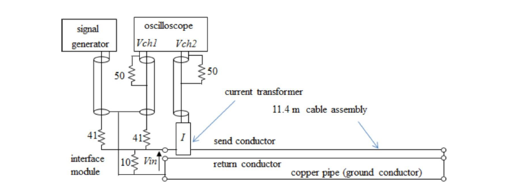
The creation of a model which simulates such an assembly requires a high degree of confidence; confidence which can only be achieved by comparing the simulation with the results of measurements carried out on a test rig. This brings with it the requirement to simulate the test equipment as well as the assembly-under-test.
Fortunately, there existed a rig which had previously been characterised using frequency response analysis. The model derived from this exercise was transformed into one which could handle transient signals, and the test equipment re-configured to deliver and monitor square wave signals.
Photos were taken of the waveforms observed on the screen of the oscilloscope.
The task then was to create a model which simulated these waveforms. Since the setup included modules which did not form part of the equipment-under-test, these modules affected the overall response of the system to the output of the signal generator. So it was necessary to simulate the effects of the interface module at the input to the test rig, the current transformer, and to correlate the sweep time of the simulation with that of the oscilloscope.
The waveforms appearing on the screen were then compared with the response of the model. Close correlation was achieved. This established a fair degree of confidence in the technique.
It was then possible to identify that part of the simulation which represents the assembly-under-test and define this as an accurate model of that assembly. That is, as a circuit diagram with values assigned to all the components.
A description of every aspect of the simulation is provided and a copy of the Mathcad worksheet which performs the calculations is included. Any electronics engineer can replicate the process, since it involves general-purpose test equipment and general-purpose software.


