The frequency-to-voltage converter has several practical uses; for example in tachometer measurements, used to determine the speed of a motor, and in electrical relay protection devices, which stop the power to connected loads if a change in frequency is detected along the power line.
In most cases, the electronic components in a frequency-to-voltage converter are many, making the circuit complex. However, here we present a simple converter that transforms frequency into voltage; see Figure 1. This a circuit that is frequently used in simple frequency meters.
So, by setting up this experiment, we are trying to determine what input frequency range permits this basic frequency-to-voltage circuit to provide reliable results in measurement. And, does it perform well at all frequencies?

Figure 1: A simple frequency-to-voltage converter circuit
Setting up the experiment
An input signal with 1Vac amplitude is injected into the circuit with the assistance of a function generator. The frequency of the signal is varied between 1Hz and 1kHz. The output voltage’s root-mean-square (RMS) value is measured using a simple voltmeter with each input signal frequency value. We can figure out the connection between the output signal’s RMS voltage level and the input signal’s frequency by dividing the output value by the input value, giving us the relationship between the two values. The outcome is expressed as a ratio, which indicates the relationship between the two numbers, which was then recorded as a graph.
The experiment assumed the following:
- The input signal amplitude was kept constant at 1Vac throughout the experiment.
- All circuit component values were kept unchanged.
- The input signal frequency was varied, starting from 1Hz to 1kHz.
- The circuit output was not connected to any load.
The output/input ratio was displayed and so were the RMS voltage values of the output signal, and the ratio between the collected values; see Figure 2.
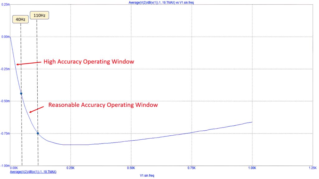
Figure 2: The relation between the input signal frequency and the output signal rms voltage at various input signal frequencies
Results
From the curve in Figure 2 we can determine that the simple frequency-to-voltage converter produces a high-precision signal for input frequencies below 40Hz. Between 40Hz and 110Hz, this accuracy deteriorates slightly but it is still acceptable. But, above 110Hz, the accuracy degrades significantly, making the circuit unsuitable for measurements of frequencies beyond that level, which requires a more complex circuit.
By Sulaiman Algharbi Alsayed, Managing Director, Smart PCB Solutions