Circuits that convert alternating current (AC) to direct current (DC) have very wide uses, one of which is a voltage-regulated loop in control- and voltage-compensation circuits.
There are many distinct varieties of these circuits, with the most basic one shown in Figure 1. This circuit has a conventional layout, but its major disadvantage is not being very precise. For a 0-5V signal, this circuit can only produce a DC voltage as low as 0.08mV; see Figure 2. Its very narrow voltage output range makes it impractical for many applications.
Figure 3 shows the AC-DC converter circuit discussed here, which provides a much more precise output. Its primary components are a pair of operational amplifiers. When 0-5Vdc is applied at its input, this circuit provides a wide DC voltage range.

Figure 1: A typical, simple, conventional AC-DC converter circuit
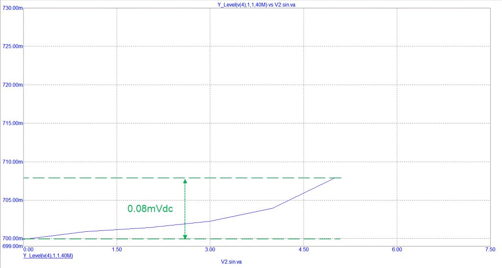
Figure 2: The narrow output voltage range generated by the simple AC-DC converter circuit
Checking the circuit’s accuracy
What we will analyse here is this circuit’s accuracy, as well as if its output voltages correspond to that of the applied AC signal.
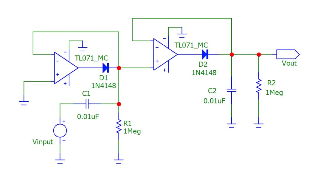
Figure 3: Typical, precision, AC-DC converter circuit
In our experiment the input signal will be gradually increased from 1Vac to 10Vac at 1Vac increments and its frequency will be varied from 1Hz to 100kHz in 10Hz steps. The measured output DC voltages will then be plotted to discover the relationship between all the variables; see Figure 4.
In addition, we assumed the following:
- All circuit component values were kept unchanged.
- The magnitude of the input signal changed between 1Vac to 5Vac (peak value).
- The temperature was kept at an ambient of 25oC.
Monitored performance
Figure 4 shows that the produced DC signal is not linear over the entire input signal’s amplitude range. The performance of the circuit may be broken down into four distinct zones, according to the rate of output DC voltage generation for each 1Vac fed at the input; see Table 1. For instance, when the input voltage is below 1Vac, the circuit will output 13mVdc for every 1Vac increment. When the input signal’s amplitude is between 1Vac and 2Vac, the circuit produces 4mVdc for every 1Vac.
For input signals above 7Vac, the circuit loses its ability to create a significant amount of output voltage. Because the output span is so narrow, running our circuit in this zone will not be useful.
It’s important to note that during this experiment, we were changing the frequency of the input signal, which proved that the circuit maintains a fairly stable output at 100kHz, which is in contrast to the input signal’s voltage magnitude.

Figure 4: The relationship between the input and output voltages

Table 1: Operating zones of our AC- DC converter
As a result, we can safely conclude that this AC-DC conversion circuit is only accurate when the amplitude of the input AC signal is relatively small. Also, the circuit exhibits four distinct zones of operational change, with each zone having its unique sensitivity rate relative to the input voltage. At an input voltage of above 7Vac, the circuit is not nearly as sensitive as first thought, making it worthless for many applications. Similarly, altering the frequency of the input signal from 1Hz to 100kHz doesn’t have much impact on the converted DC voltage.
These results are important to note, since they show that each AC-DC converter circuit has an optimal operation zone, which determines the circuit’s suitability for an application.
By Dr Sulaiman Algharbi Alsayed, Managing Director, Smart PCB Solutions