The half-wave rectifier circuit is essential to most AC-to-DC converters. Because of the benefits it offers, this circuit based on op-amps is more popular than conventional rectifiers. One such advantage is that it provides reasonable over-voltage protection, so in case of a failure, the downstream connected circuits will not see a highly-damaging current, unlike conventional rectifier circuits, which are usually very venerable to passing high currents.
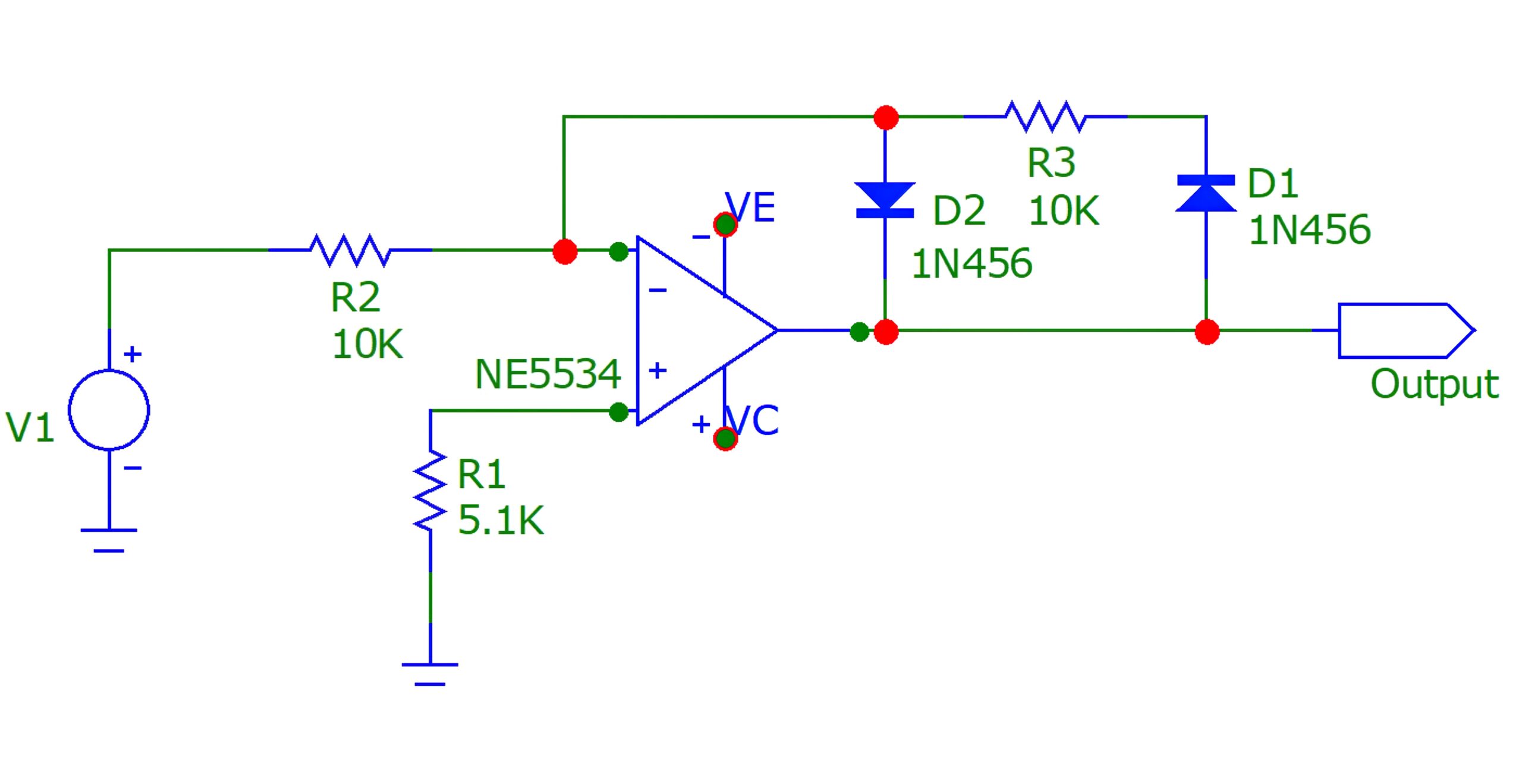
Figure 1 shows one popular op-amp-based half-wave rectifier circuit, consisting of a single op-amp and a diode bridge, with its output shown in Figure 2.
This circuit can be used in many applications, but an important question is, what frequency operating window can we use it with?

Figure 1: Typical op-amp-based half-wave rectifier circuit
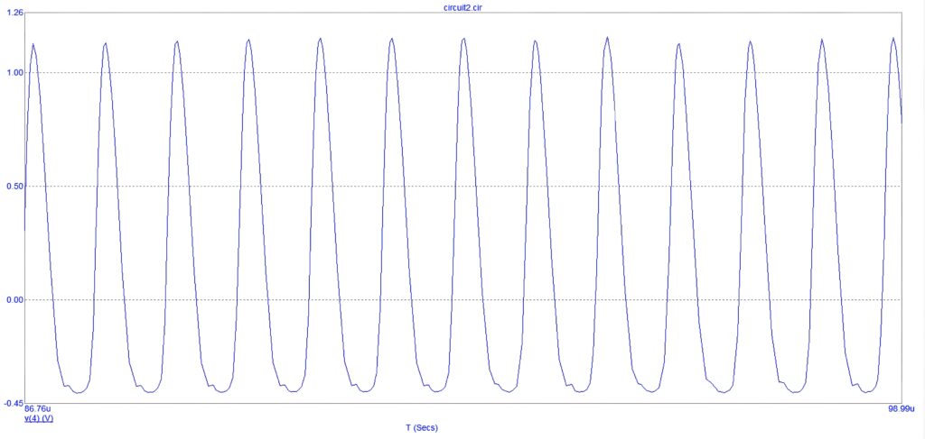
Figure 2: Half-wave rectifier circuit output signal
Experiment methodology
We connect the op-amp-based half-wave rectifier circuit to a function generator with a sinusoidal signal. The input signal’s frequency changes gradually, at fixed intervals from 1Hz to 2MHz – there’s no need to go above it.
The values of the input frequencies and output amplitudes are measured and tabulated accordingly, to determine the relationship between the two variables.
The experiment was conducted assuming the following:
- The input signal amplitude was kept constant at 1Vac.
- The input signal DC offset was kept at 0Vdc.
- The op-amp supply circuit is kept stable.
- R1, R2, R3, D1, D2 and the op-amp were left unchanged.
- The voltage power supply was kept constant, to avoid interfering with the collected data.
- The circuit’s output was not connected to any load, to focus on studying the two variables only: input frequency and output amplitude; see their relationship in Figure 3.
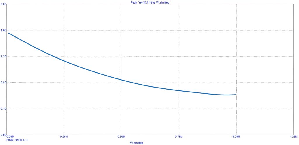
Figure 3: The output signal amplitude vs. the input signal frequency
From the curve in Figure 3 we can conclude that the half-wave rectifier circuit operates better at lower frequencies. The higher the input frequency, the lower the output amplitude.
Another observation is that the relationship between the two parameters is exponential, implying that the output signal amplitude deteriorates severely when the circuit operates at a higher frequency.
By Sulaiman Algharbi Alsayed, Managing Director, Smart PCB Solutions