Resistor multiplier circuits are widely used in circuit design, as they amplify the actual resistance through a negative-loop operational amplifier combination. Figure 1 shows one such simple circuit that can provide high resistance. It uses the LT1012 op-amp, which offers a broad voltage supply range.
To calculate the input resistance of such a circuit, there’s an equation, namely Rin = R1 * (1 + R3/R2). For the circuit in Figure 1, Rin is the input resistance seen by the power supply, V1. The values of resistors R1-R3 can be chosen based on the application needs.
Resistor multiplier circuits
Resistor multiplier circuits are primarily used to divide a voltage into a fraction of its original value. This is frequently used in power supplies and sensor circuits to establish a stable reference voltage.
They are also used in sensor circuits to scale or attenuate the sensor’s output voltage, which aligns with the input range of a microcontroller or an analogue-to-digital converter. Additionally, resistor multiplier circuits are useful in monitoring battery voltage levels in electronic systems that run on batteries. They trigger alerts or actions when the voltage falls below a certain threshold. In communication systems and audio circuits, resistor multipliers are used to attenuate signals to desired levels with minimal distortion.
In one of my projects, I considered using this particular circuit, but I had concerns about the equation’s accuracy when the power supply voltage decreases during circuit operation. I wondered about the equation’s accuracy and until what supply voltage. Additionally, I also wanted to determine the impact of a declining power supply voltage on the circuit’s performance. Would the circuit maintain the same resistance multiplication ratio at various power supply voltages? That’s why this experiment was set up.

Figure 1: A simple resistance multiplier circuit
The experiment
The circuit shown in Figure 1 was chosen for the experiment due to its simplicity. Although there are various other circuits available, they mainly revolve around the same design and concept.
During the experiment, various power supply voltages were applied, and at each step the circuit’s resistance was calculated using the input voltage and current. The applied voltage ranged from 1Vdc to 20Vdc, which is the operating range of the LT 1012 op-amp. All remaining components were kept unchanged.
The measured circuit input resistance was then plotted; see Figure 2. The curve reveals that the relationship between the power supply voltage and the circuit input resistance is not constant, which departs from the Rin = R1 * (1 + R3/R2) equation. This equation only holds true at a single point on the curve, when the supply voltage is at 13.4Vdc. When the voltage falls below or rises above this 13.4Vdc point, the circuit shows higher and lower resistances.
Also, another observation was made: The curve in Figure 2 shows a linear relationship between the power supply voltage and circuit resistance changes, at a linear ratio of about 82.3Ω/Vdc.
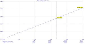
Figure 2: Circuit input resistance vs power supply voltage
This leads us to conclude that the resistance multiplier circuit in Figure 1 doesn’t provide a constant resistance multiplication ratio as per the commonly-used equation Rin = R1 * (1 + R3/R2).
From the above, a new equation arises, namely Rin = 82.3 * R1 * (1 + R3/R2), which describes the resistance multiplier performance more accurately. This experiment and its findings are significant for circuit designers, considering this circuit’s wide implementation. Understanding the impact of the power supply voltage impact on circuit performance is crucial, helping designers to create more accurate circuits.#