There are many designs of low-power alarm circuits. Figure 1 shows one of the most commonly used, which is also inexpensive and quick to assemble, consisting of only a few components – a TTL chip, Zener diode, resistor and a speaker.
The circuit works as follows: The TTL chip is a voltage comparator, which compares the input voltage with the Zener voltage. When the input voltage drops below that of the Zener, the TTL output goes high, turning the speaker on. When the input voltage stays above the Zener voltage, the TTL chip output goes low, which turns off the speaker.
A beneficial feature of this circuit is that it draws extremely low current in standby mode, i.e., when the input voltage is higher the Zener voltage, or 144µA. This makes it suitable for many applications where power consumption is a concern, such as battery-powered devices. For example:
- In battery-powered devices the circuit monitors the battery voltage and sounds an alarm if the voltage drops below a certain level.
- In security systems the circuit can monitor a break-in or another security event.
- In industrial applications the circuit can monitor the voltage of a power supply or other electrical system.
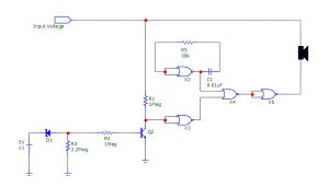
Figure 1: A typical TTL-based low-power alarm circuit
Figure 2 shows this circuit’s performance, with the x axis representing the input voltage and the y axis the current passing through the 100-ohm speaker. Threshold voltage is the voltage at which the current through the speaker begins to increase significantly. In our case this is around 5Vdc, which is the nominal voltage of the Zener diode.
When the input voltage is below 5Vdc, the current passing through the speaker goes high, operating the speaker; above 5Vdc this current is very small. In our case, the maximum current that flows through the speaker is around 144µA.

Figure 2: The current passing through the speaker
TTL is a type of logic gate that operates at a supply voltage of 5Vdc. If the power supply voltage goes above or below this level, the circuit’s performance will change, too. Standby current is the current that flows through the circuit when it is not actively doing anything. The standby current of a TTL circuit is typically very low – in the microampere range.
Experiment setup and results
Questions relating to this circuit and its performance include:
- What happens if the power supply voltage (5Vdc) drops or rises?
- What will the standby current be?
- Will the circuit still be stable?
Since this circuit is commonly found in many applications, it is very important to determine the answers to these questions, so we set up the following experiment.
We check the circuit’s performance for several power supply voltages – 3Vdc, 4Vdc, 5Vdc, 6Vdc and 7Vdc. For each one we plot the magnitude of the current passing through the speaker, but also the standby current (when the input voltage above 5Vdc) vs. the power supply voltage (4-7Vdc).
We used a 5Vdc Zener diode; different Zener diodes can be used for threshold voltages different to 5Vdc.
We also assumed the following:
- All circuit component’s values were kept unchanged.
- The ambient temperature was kept at 25o
The resulting plots from the experiment are shown in Figures 3-4.
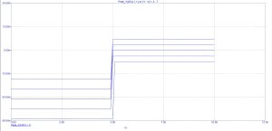
Figure 3: The speaker current vs. the input voltage at various power supply voltage levels
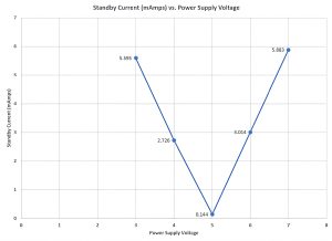
Figure 4: Speaker current vs. power supply voltage
These results show that our circuit in Figure 1 draws very low current when in standby mode, or 5Vdc power supply voltage, i.e., in this mode it draws only 144µA. However, the experiment also shows that the circuit draws very high current (in standby mode) when the power supply voltage deviates from the nominal 5Vdc; see Figure 4.
This finding is very important for circuit designers to consider, since they must be aware of this circuit’s limitations. A circuit designer will then either use a stable or regulated power supply to support this circuit or consider using a different design if low power consumption is crucial for the application.
By Dr Sulaiman Algharbi Alsayed, Managing Director, Smart PCB Solutions