The rising popularity of time of flight (TOF) cameras in industrial applications, particularly in robotics, is attributed to their exceptional depth computing and infrared (IR) imaging capabilities. Despite these advantages, the inherent complexity of the optical system often constrains the field of view, limiting standalone functionality. A 3D image stitching algorithm, designed for a supporting host processor, eliminates the need for cloud computation. This algorithm seamlessly combines IR and depth data from multiple TOF cameras in real time, producing a continuous, high-quality 3D image with an expanded field of view beyond standalone units. The stitched 3D data enables the application of state-of-the-art deep-learning networks – particularly valuable in mobile robotics applications – to revolutionise the visualisation and interaction with the 3D environment.
Stitching captured data
TOF cameras stand out as exceptional range imaging systems, utilising TOF techniques to determine the distance between a camera and each point in an image. This is achieved by measuring the round-trip time of an artificial light signal emitted by a laser or an LED. TOF cameras provide precise depth information, making them valuable tools for applications where accurate distance measurement and 3D visualisation are crucial, such as robotics and industrial technology applications, including collision detection and human detection over 270° field of view (FOV) for safety.
The ADTF3175 TOF sensor can achieve a calibrated 75° FOV. However, challenges arise when an application’s FOV exceeds this region, requiring multiple sensors. Integrating data from individual sensors to provide comprehensive analytics for the entire view can pose difficulties. One potential solution involves having sensors execute an algorithm on a partial FOV and transmitting the output to a host for collation. Yet this approach faces issues such as overlap zones, dead zones and communication latencies, making it a complex problem to address effectively.
An alternate approach involves stitching the captured data from all sensors into a single image and subsequently applying detection algorithms on the stitched image. This process can be offloaded to a separate host processor, relieving the sensor units from the computational load and providing room for advanced analytics and other processing options. However, it’s important to note that traditional image stitching algorithms are inherently complex and can consume a significant portion of the host processor’s computational power. Furthermore, sending to and stitching in the cloud is not possible in many applications due to privacy reasons.
ADI’s algorithmic solution can stitch the depth and IR images from the different sensors, using the point cloud projections of the depth data. This involves transforming the captured data using camera extrinsic positions and projecting it back into 2D space, resulting in a single continuous image.
This approach results in minimal computation, which helps achieve real-time operating speeds on the edge and ensures that the compute capacity of the host processor remains available for other advanced analytics.
Description of a solution
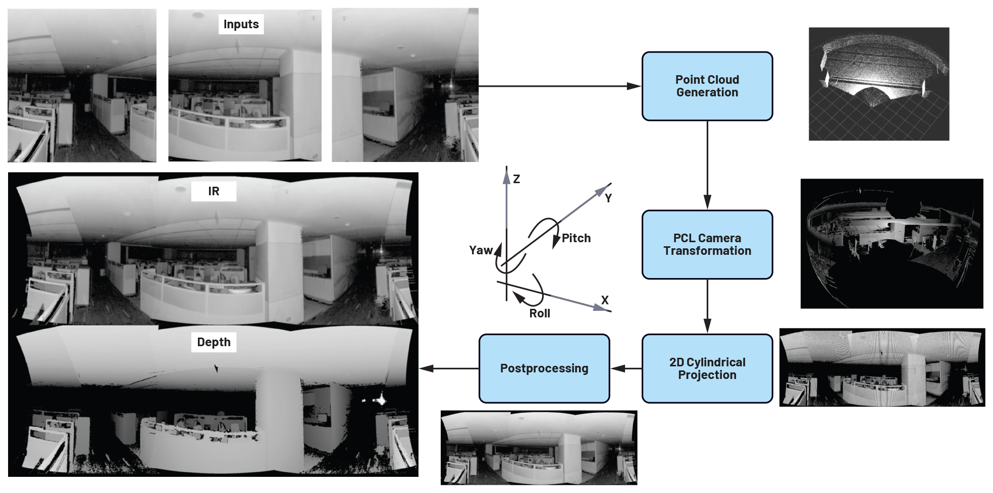
ADI’s 3D TOF solution operates in four stages; see Figure 1:
- Pre-process IR and depth data: Time synchronisation and pre-processing of IR and depth
- Project depth data into 3D point cloud: Utilise camera intrinsic parameters to project depth data into a 3D point
- Transform and merge points: Transform points using the camera’s extrinsic positions and merge overlapping
- Project point cloud into 2D image: Employ cylindrical projection to project the point cloud back into a 2D image.
A host machine is connected to multiple TOF sensors over a high speed connection such as USB. It collects depth and IR frames and stores them in a queue.
Depth and IR frames from each sensor received by the host are captured at different instances of time. To avoid temporal mismatch due to the movement of objects, inputs from all sensors need to be synchronised to the same instance of time. A time synchroniser module is used that matches incoming frames based on timestamps from the queue.
A point cloud is generated on the host using the synchronised depth data for each sensor. Each point cloud is then transformed (translated and rotated) based on its respective camera positions in the real world. The transformed point clouds are then merged to form one single continuous point cloud, covering the combined FOV of sensors.
The combined point cloud of the FOV is projected to a 2D canvas using a cylindrical projection algorithm also known as front view projection; see Figure 4. In other words, the algorithm projects each point of the merged point cloud onto a pixel in the 2D plane, which results in a single continuous panoramic image covering the combined field of view of all the sensors. This results in two 2D stitched images: one for stitched IR and another for stitched depth images projected onto 2D planes.
Enhancing projection quality
Projecting the 3D combined point cloud onto a 2D image still does not give good quality images. The images have distortions and noise, which affects visual quality and would also adversely affect any algorithm that runs on the projection; the three key issues are listed here:
1. Projecting invalid depth regions
The depth data of the ADTF3175 has an invalid depth value of 0mm for points that are beyond the operational range of the sensor (8000mm). This results in large void regions on the depth image and forms incomplete point clouds. A depth value of 8000mm (the largest depth supported by the camera) was assigned to all the invalid points on the depth image and a point cloud was generated with it. This ensured that there were no gaps in the point cloud.
2. Filling unmapped pixels
While projecting the 3D point cloud onto a 2D plane, there are unmapped/unfilled regions in the 2D image. Many point cloud (3D) pixels get mapped to the same 2D pixel, hence several 2D pixels remain blank, resulting in a stretch pattern as shown in Figure 6. To fix this, a 3 × 3 filter was used that fills the unmapped pixels with the average IR/depth value of its neighbouring 8 pixels that have valid values. This resulted in a more complete output image formation and artefacts were removed; see Figure 6.
3. Noise generated by overlapping points
Because of the cylindrical projection algorithm, many points on the overlapping region end up getting the same resting coordinates on the 2D projected output. This creates noise as the background pixels overlap those in the foreground. To fix this problem, the radial distance of each point is compared with an existing point, with the point being replaced only if the distance from the camera origin is smaller than the existing point, improving projection quality; see Figure 7.
Suitable for edge computing systems
This algorithm can stitch images from different cameras with less than 5° of overlap compared to a minimum of 20° of overlap as needed by traditional key points matching algorithms. This approach needs very little computation, making it an ideal candidate for edge systems. The integrity of the depth data is retained post-stitching since there is no image distortion. This solution further supports the modular implementation of the ADTF3175 sensors to obtain the desired FOV with minimal loss.
The FOV expansion is not confined to the horizontal dimension, and the same technique can be used to expand the view vertically to obtain true spherical vision. The solution runs on an Arm V8, 6-core edge CPU at 10fps for four sensors providing 275° FOV. The frame rate goes up to 30fps when only two sensors are used.
One of the key benefits of this approach is the massive computation gain achieved – more than 3× gain in basic computation.
By Rajesh Mahapatra, Senior Manager, Anil Sripadarao, Principal Engineer, and Swastik Mahapatra, Senior Engineer, all with Analog Devices (ADI)