Any application that uses rechargeable batteries requires improved efficiency and energy as well as cost savings. One other challenge, however, is charging downtime. This area must be focused on, to advance the capabilities of battery management systems (BMS) and power distribution units (PDU), enabling system operation close to 24/7.
A BMS uses integrated firmware and hardware to manage battery packs. When paired with telematics, the BMS provides real-time data on the health and status of the battery. Typical BMS functions include cell voltage monitoring and balancing, and fuel gauge and temperature monitoring.
A PDU, on the other hand, provides electrical protection for the battery, and communicates directly with the BMS to safely distribute power. Its features include power monitoring, autonomous trip capabilities, current sensing and fast switching.
Together, the BMS and PDU play a critical role in safeguarding batteries from various performance, operational and safety problems.
A good BMS is essential
Any operation today that uses lithium-ion battery packs can rely on data and insights to make smart decisions. A good BMS provides valuable information about equipment and performance that, when analysed carefully, can offer insights for even more informed decisions or avoid catastrophes.
With their high energy density and low memory effect, lithium-ion batteries can survive more charging cycles independent of the state of charge compared to traditional lead-acid batteries. This allows lithium-ion batteries to reach a usable charge faster and to tolerate shorter, more frequent charging times, to keep the systems they support at full charge.
This opportunistic charging has driven a number of trends in both industrial and commercial applications, and has increased demand for more powerful energy infrastructure, more charging stations for vehicles, and more sophisticated BMSs. In addition, an advanced, high-quality BMS goes beyond simple monitoring functions to provide operators with real-time data on their equipment or vehicle fleet. For example, operators can use this data to anticipate preventive maintenance needs across a fleet, provide valuable insights into equipment use patterns, track battery usage, temperature and charging status to glean insights about opportunistic-charging habits, and a lot more.
Developing BMS electronics
Because system designers are under pressure to deliver more complex products with more features and functionality on a tight budget and tight schedule, comprehensive simulation tools are critical. They allow designers to build replicas of the system to ensure that all its components work perfectly before the labour- and cost-intensive manufacturing processes begin. These simulations deliver real-world views of crucial factors, such as a component temperature limits, before any product is built, in order to speed up the development process.
In developing the electronics for a BMS, start by considering the temperature, current and voltage requirements of the application.
Then move on to the architecture and the position of any sensor. Here, it’s important to assess the best place for the sensor relative to the data and signal transfer components. Third-level requirements are data rates and wire sizes, among other factors.
One of the trickiest parts for system designers is determining how to lay out the printed circuit board (PCB). Typically, PCB space is at a premium and there is a lot of functionality to pack in, heat to dissipate and EMI noise to eliminate.
Proper PCB development is essential for the rest of the BMS to work optimally. TE offers ECAD files that are compatible with leading PCB design platforms, enabling designers to build a solution with some 40,000 TE products. ECAD files also help quickly select TE parts for a board so OEMs can bring their product to market faster.
BMS power management
When thinking about power management within the BMS, there are several important factors to consider. It is recommended that designers start with the voltage level and current to determine the required power for charging.
The design of relays and contactors is crucial for power management. TE is expanding its portfolio of DC contactors for wider nominal currents (50-500A), which can be used in electrical forklifts and mid-sized autonomous mobile robots (AMRs). TE contactors are typically fitted with a normally open (NO) contact and they suppress the arc that is produced when interrupting heavy motor currents. These contactors can handle breaking currents up to 2000A.
Considering bi-directional charging and a full battery, this requires an additional solution to prevent charging the battery. Here, one go-to solution is a resistor, the passive component that reduces voltage or limits the current flowing through a circuit. A resistor can also absorb energy and dissipate energy as heat. Hence, the materials used in a resistor’s composition perform a critical role in enabling performance reliability and stability, particularly for high-voltage, high-power, high-stability/accuracy, or high-current applications.
Choosing the right type of resistor is crucial for designing a circuit with the power, accuracy, current, or voltage needed to efficiently power any device. The TE portfolio features two types of resistors: fixed resistors (including surface mount, through-hole, and chassis mount), which offer one resistance value and are used in almost all applications; and variable resistors (including potentiometers and trimmer potentiometers, also known as trim pots), which offer broad resistance values and are predominantly used to control either current or voltage by changing the resistance value.
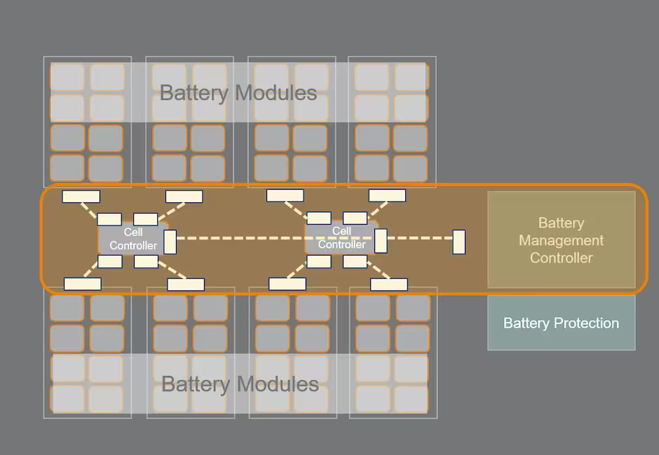
Building a sophisticated BMS
The typical BMS is compact and complex. Engineers can choose its architecture depending on cell type, pack layout and the quantity of wire-to-board signal connections and their routing. The BMS relies on dependable signal and data connectors to function well. To get the best, most-advanced performance out of a BMS requires selecting the best, most-reliable connectors to power it. Hence, when designing a more sophisticated BMS, look for connectivity solutions that have these traits:
- Flexibility to handle a variety of functions and applications. Look for components that function well in various configurations, and cables that are made to bend, twist or fold in tight spaces without loss in performance.
- Vibration resistance due to the operating conditions within more rugged equipment or v Connectors with locking mechanisms are a good place to start, to ensure a vibration-resistant connection.
- Ruggedised components and temperature regulation to survive harsh industrial environments. Look for components that can withstand operating temperatures between -40°C and 125°C, and consider sealed solutions to protect connectors. For example, TE’s Dynamic Series covers a wide range of expanding connector types to meet non-standard solutions, including slim wire-to-wire connectors suitable for narrow spaces, connectors with low interference risk and streamlined design, and a special IP67 product version that is dust- and water-resistant for use in harsh conditions.
- Compact size with powerful performance capabilities. Look for connectors with a higher number of pins in a very small space, to ensure that the component is as compact as possible whilst still delivering the high power necessary for the application. Also look for components with a low pitch height. For example, many of TE’s ERNI products are under 1.80mm, and TE’s Dynamic Mini Series features 1.80mm pitch height with up to 44 pins.
- Security, to protect the operation. Consider a click-audible connector to help secure mating and prevent disconnecting.
- Reliable charging control and tracking. Look for components that provide seamless, high-speed communications and data transfer, plus dependable signal transfer.
By Dr. Daniel König, Strategic Business Development, TE Connectivity