Humanoid robotics is changing what motor drive electronics must do. In traditional industrial drives, the inverter is usually in an outside cabinet, connected to the motor by cables. However, in humanoid robots, actuators must fit into joints that replicate how people move – like the shoulder, elbow, wrist and, even, fingers. This architectural shift forces power electronics to migrate inside the motor housing, where space, thermal dissipation and dynamic response requirements are significantly more demanding.
Humanoid actuation trends
Two parallel directions are emerging in humanoid actuation: High‑power joints and extreme miniaturisation.
Hips and torso require higher current and benefit from lower conduction losses and improved thermal handling. Wrists, hands and fingers require maximum integration where sensors and even current shunts approach the size of the power IC itself.
As switching devices continue shrinking, sensing technology may become the dominant size limitation rather than power semiconductors. Future actuator electronics may integrate current sensing directly into the power module to overcome this bottleneck.
System‑level constraints in humanoid joints
A humanoid joint actuator simultaneously requires high torque density (large torque from a very small motor), high dynamic bandwidth for natural motion control, low thermal rise in confined spaces, high electrical efficiency, as well as minimal weight and volume. Because the inverter is a physical part of the actuator, cabling inductance and parasitics must also be kept to a minimum. Here, the drive needs to fit the power stage, sensing, control and communication into a small footprint, which is usually round to fit the shape of the motor.
The main point is that power density, not just efficiency, becomes the most important design metric. You can’t use a drive that is big but works well; on the other hand, a small drive with high switching losses can’t get rid of heat inside a sealed joint.
Integrated inverter architecture
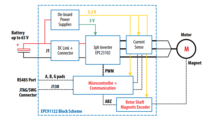
A typical joint‑integrated inverter includes three‑phase half‑bridge power stage, gate drivers, microcontroller for field‑orientated control, rotor position sensing (magnetic encoder), phase current sensing, DC link capacitors, communication interface and on‑board auxiliary power supply.
To fit inside a motor housing, the electronics are implemented on a circular PCB matching the motor diameter. Ceramic DC‑link capacitors are preferred due to volumetric efficiency and low ESL, enabling fast current transitions.
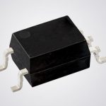
The heart of the system can be a monolithic three‑phase GaN power module that integrates transistors and gate drivers into a single compact package. This drastically reduces loop inductance and eliminates layout‑dependent switching behaviour typical of discrete MOSFET solutions.
GaN enables embedded drives
Traditional silicon MOSFET motor drives usually operate at switching frequency of under 20kHz, since beyond that point switching losses rise quickly and thermal management becomes difficult. Humanoid robot joints, however, benefit from operating at much higher PWM frequencies, about 80-100kHz. At these frequencies the current ripple is significantly reduced, torque delivery becomes smoother, acoustic noise is greatly diminished and the control loop can run with higher bandwidth. An additional advantage is that the motor itself can be made smaller for the same performance.
Gallium nitride (GaN) devices introduce a fundamentally different behaviour compared to silicon. They combine very fast switching speed with no reverse recovery charge. This enables higher frequencies plus the elimination of the deadtime required for a silicon MOSFET to recover from diode conduction. Because of this, GaN power stages can switch efficiently around 100kHz whilst still keeping temperatures manageable inside a compact joint enclosure. The much lower switching energy and extremely short dead times improve linearity and torque accuracy at low speed – a crucial requirement for precise robotic manipulation.
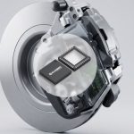
The EPC91122 evaluation board
The reference platform shown in Figure 1 is an example of an inverter that integrates a complete three‑phase BLDC inverter into a circular PCB (Figure 2) intended for installation inside robotic joints. The inverter core is a GaN three‑phase power stage rated to 100V, integrating three half‑bridges, gate drivers, bootstrap circuitry and level shifting within a single compact package. The board delivers phase current of up to 20Arms (28A peak) and is typically operated around 100kHz PWM with very short dead time, enabling low torque ripple and high control bandwidth.
All functional subsystems required for a standalone servo drive are included: the motor‑control microcontroller, magnetic rotor encoder interface (1024 ppr class), phase‑current sensing, DC‑bus voltage sensing, auxiliary 5V and 3.3V supplies, and RS‑485 communication. The inverter electronics occupies a space of 32mm inner diameter within a 55mm mechanical frame, reducing power loop inductance and improving dynamic response.
The wide input voltage range (approximately 10-65V) makes the platform suitable for battery‑powered robotics. Ceramic DC‑link capacitors and short current paths allow fast current transients, whilst integrated protection and programming interfaces simplify firmware development and rapid evaluation in actuator prototypes.
Changed motor drive priorities
Embedding the inverter inside the motor fundamentally changes motor drive design priorities. Power density, switching speed and integration replace traditional cabinet‑level considerations. GaN technology enables this transition by combining low switching loss with high‑frequency operation, making compact, efficient joint actuators feasible.
As humanoid robotics advances toward higher dexterity and natural motion, highly integrated motor drives are likely to become the standard architecture, not an experimental approach.
By Maurizio Di Paolo Emilio, Director of Global Marketing Communications, Efficient Power Conversion (EPC)