A reverse-voltage protection circuit is a standard safety precaution that is included in most electrical equipment. When the supplied voltage is of the right polarity (forward voltage), the reverse-voltage protection circuit acts as a buffer, to ensure that the same input voltage is sent to the output and the load connected to it. When the supplied voltage is of reverse polarity, the circuit’s output voltage falls to zero volts or very near it, safeguarding the load from reverse voltages.
Protection circuits
There many different circuit designs to guard against reverse voltage, one of which is shown in Figure 1. Here the power supply is connected to the circuit’s input (Vin), with the protected circuit being attached to its output (Vout). When the polarity of the input voltage is of the right polarity, Vout should (in theory) be identical to Vout.
To determine whether this is the case, we set up this experiment.

Figure 1: A typical reverse-voltage protection circuit
For the experiment we considered the following:
- Throughout the experiment the input voltage was changed between -10Vdc and 10Vdc;
- All circuit component values were kept unchanged;
- The circuit output was connected to a 10K load. It’s worth noting that there are no significant changes in the output voltage if the load was changed.
Monitored performance
The ratio between the output and the input voltages was displayed following their readings; see Figure 2. To determine their relationship, we plotted the readings too – see the dashed line in Figure 2. This shows that the circuit does not deliver a linear output (in relation to the input voltage) when the input voltage is between 0Vdc and 3.8Vdc. In that range, the circuit output is 0.6Vdc lower than the input voltage.
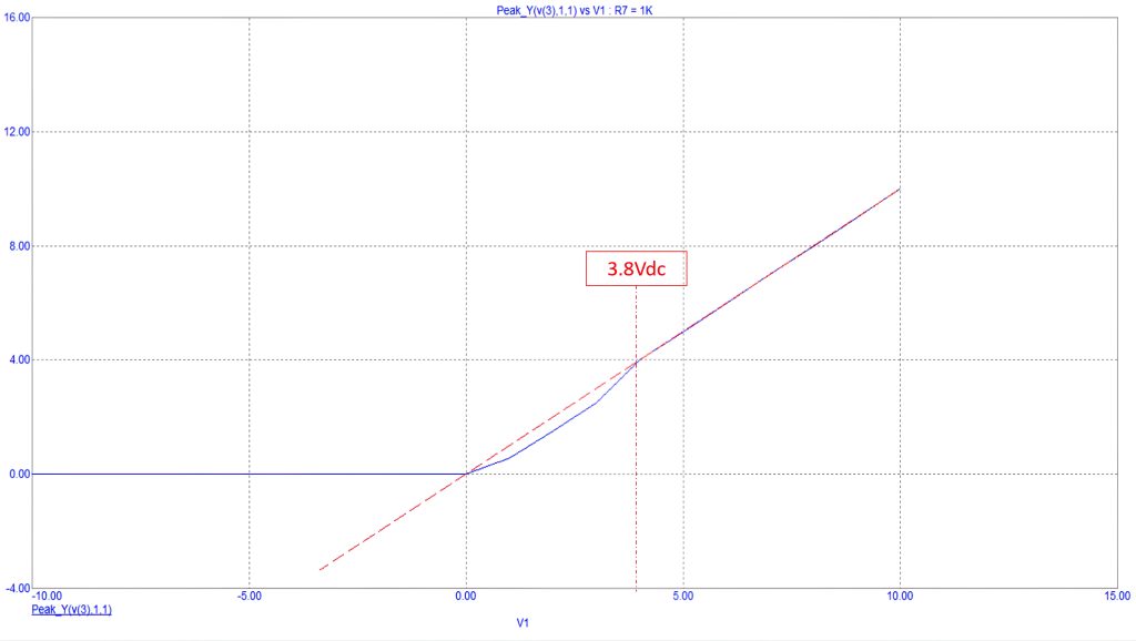
Figure 2: Relation between the input and output voltages
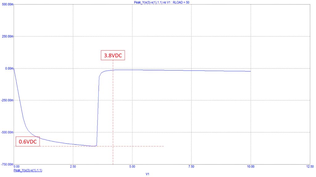
Figure 3: Magnified circuit response curve of the relationship between the input and output voltages
Magnifying the curve of Figure 2 shows the exact shape of the circuit response; see Figure 3.
We can safely conclude that the reverse-voltage protection circuit could not deliver a linear output voltage (in relation to the applied input voltage) when the input voltage is above 0Vdc and less than 3.8Vdc, but it shows a perfect linear relation when the applied input voltage is above 3.8Vdc. These findings are very important for circuit designs, since it means that for an operating voltage of between 0Vdc and 3.8Vdc it is not recommended to use a reverse-polarity protection circuit as it will reduce the voltage passing through to the protected circuit (the load) by about 0.6Vdc. For that voltage range, a more complex reverse-voltage protection circuit is required.
By Dr Sulaiman Algharbi Alsayed, Managing Director, Smart PCB Solutions