Function generator circuits generate different waveforms – sinusoidal, triangular and rectangular. Such a circuit can generate just one type of signal or multiple waveforms.
Here we will examine a popular function generator’s (Figure 1) behaviour and performance when one its outputs is connected to a low-resistance load. This information is important for circuit designers, when selecting the applications for this circuit.
The setup
The selected circuit consists of three op-amps, each being able to generate rectangular, triangular and sinusoidal signals.
Figure 2 shows the signals when the circuit’s outputs are not connected to a load; as you can see, all signals look stable.

Figure 1: A popular function generator circuit

Figure 2: Function generator signals when none of the outputs are connected to a load
The circuit’s power is kept fixed at +5Vdc and -5Vdc. A variable load resistor is connected to each output, to examine the stability of the circuit’s outputs at any given scenario.
The resistor is first connected to the rectangular output, with the signal shapes monitored when the resistor’s value reduces. The same steps are repeated with the load resistor connected to the triangular and sinusoidal signal outputs.
Scenario 1: Loading the rectangular output
By plotting the circuit signals’ peak-to-peak values at various load resistances on the rectangular output, the circuit delivered stable outputs for the rectangular, triangular and sinusoidal signals, when the load resistance is over 254 Ohms. Below this value, all signals start to rapidly deteriorate; see Figure 3.

Figure 3: Signal behaviour when a load resistor is connected to the circuit’s rectangular output
Scenario 2: Loading the triangular output
When the load resistor is connected to the triangular signal output, the circuit shows a very stable rectangular signal. However, the triangular and sinusoidal output signals deteriorate rapidly for load resistances below 130 Oms; see Figure 4. Still, this circuit shows better performance in this setup compared with scenario 1.

Figure 4: Signal behaviour when a load resistor is connected to the circuit’s triangular output
Scenario 3: Loading the sinusoidal output
When the load resistor is connected to the sinusoidal signal output, the circuit shows a very stable behaviour at both the rectangular and triangular signal outputs. However, only the sinusoidal output signals deteriorate rapidly for load resistances below 132 Oms. The circuit shows better performance in Scenario 3 compared with Scenarios 1 and 2; see Figure 5.
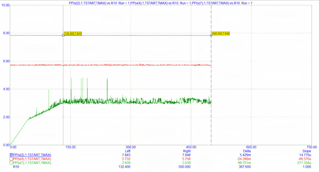
Figure 5: Signal behaviour when a load resistor is connected to the circuit’s sinusoidal output
Hence, results show that the function generator circuit is not providing ideal performance when load resistance drops below a certain level (threshold resistance). This threshold resistance is not even the same with each output signal. This clearly indicates that loading one output of the circuit will impact the other outputs, and that some applications call for more robust and complex function generator circuits, to operate outside the operating windows defined in this experiment.
By Sulaiman Algharbi Alsayed, Managing Director, Smart PCB Solutions